'XHWRRXUSROLF\RIFRQWLQXRXVSURGXFWLQQRYDWLRQVRPHVSHFL¿FDWLRQVPD\FKDQJHZLWKRXWQRWL¿FDWLRQ
©
/*(OHFWURQLFV86$,QF(QJOHZRRG&OLIIV1-$OOULJKWVUHVHUYHG³/*´LVDUHJLVWHUHGWUDGHPDUNRI/*&RUS
5()5,*(5$17'(6,*1 | 139
Refrigerant Piping Design & Layout Best Practices
LAYOUT BEST PRACTICES
Selecting Field-Supplied Copper Tubing
Anticipated Linear
Expansion (LE) (inches)
Nominal Tube Size (OD) inches
1/4 3/8 1/2 3/4 1 1-1/4 1-1/2
1/2
R
1
6789111213
L
2
38 44 50 59 67 74 80
1
R
1
9 101113151718
L
2
54 63 70 83 94 104 113
1-1/2
R
1
11 12 14 16 18 20 22
L
2
66 77 86 101 115 127 138
2
R
1
12 14 16 19 21 23 25
L
2
77 89 99 117 133 147 160
2-1/2
R
1
14 16 18 21 24 26 29
L
2
86 99 111 131 149 165 179
3
R
1
15 17 19 23 26 29 31
L
2
94 109 122 143 163 180 196
3-1/2
R
1
16 19 21 25 28 31 34
L
2
102 117 131 155 176 195 212
4
R
1
17 20 22 26 30 33 36
L
2
109 126 140 166 188 208 226
1
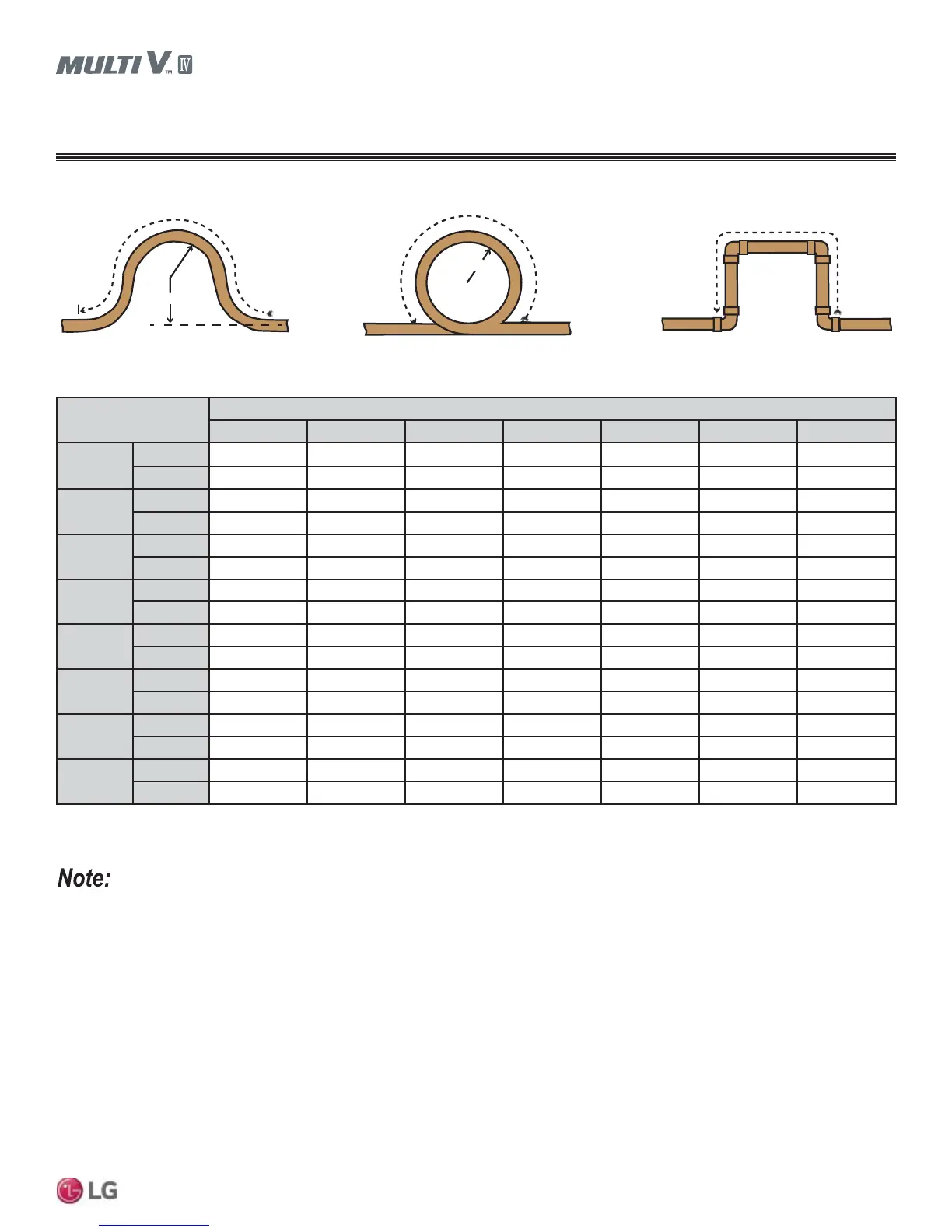
R = Centerline Length of Pipe.
2
L = Centerline Minimum Radius (inches).
Figure 27: Coiled Expansion Loops and Offsets (Plan View).
Table 53: Radii of Coiled Expansion Loops and Developed Lengths of Expansion Offsets.
Large Tubing U-bend (>3/4 in.) Loop Small Tubing U-bend (<3/4 in.)
R
L
R
L
L
All expansion Loops and Offsets should be installed in the horizontal plane to prevent the possibility of trapping oil. Loops and Offsets in verti-
cal risers should also be installed in a horizontal plane.