150 |(/(&75,&$/&211(&7,216
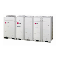
MULTI V IV Outdoor Unit Engineering Manual
'XHWRRXUSROLF\RIFRQWLQXRXVSURGXFWLQQRYDWLRQVRPHVSHFL¿FDWLRQVPD\FKDQJHZLWKRXWQRWL¿FDWLRQ
©
/*(OHFWURQLFV86$,QF(QJOHZRRG&OLIIV1-$OOULJKWVUHVHUYHG³/*´LVDUHJLVWHUHGWUDGHPDUNRI/*&RUS
DIP SWITCH SETTINGS FOR
GEN4 EQUIPMENT
Generation 4 Equipment
The latest versions of LG’s indoor units and outdoor (air / water source) units are designated Generation 4 (Gen 4). For Gen 4 units to oper-
ate with Gen 4 features, the air conditioning system must meet the following requirements:
• All indoor units, heat recovery units, and air / water source units
must be Gen 4.
• All air / water source units must have Gen 4 software
installed.
• Air / water source units DIP switch 3 must be set to ON
(factory default setting is OFF).
• All controllers must support Gen 4 features.
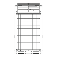
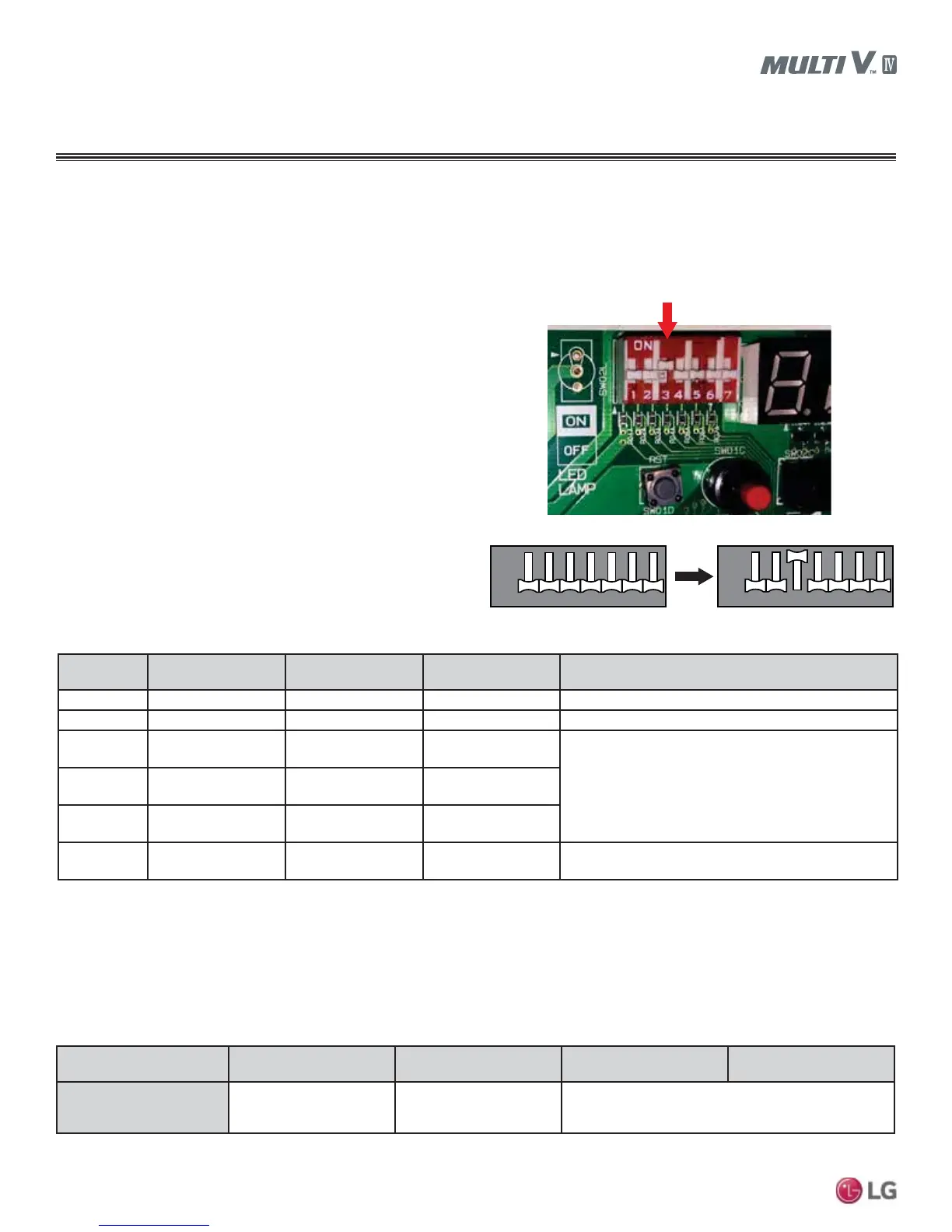
The figure at right shows the ODU DIP switch. The "System Com-
ponent Combinations and Operation Status" table lists how combin-
ing different components will affect system operation. The "Serial
Numbers or Air / Water Source Units with Gen 4 Software" table lists
the serial numbers of air and water source units that have Gen 4
software. All air and water source units, indoor units, heat recovery
units, and controllers in a system must be Gen 4 compatible or the
system will not operate with Gen 4 features.
Air / Water
Source Units*
Indoor Unit(s)** Heat Recovery Unit(s)
Outdoor Unit DIP
Switch No. 3
Operation Status
Gen 4 Gen 4 ONLY Model 2A ONLY Must be ON System will operate WITH Gen. 4 features.
Gen 4 Gen 4 ONLY Model 2A ONLY OFF System will operate but WITHOUT Gen. 4 features.
Gen 4 Gen 4 ONLY
Any combination of
Models 1A, 2A
Must be OFF
(factory default)
Does NOT include Gen. 4 features. System will not
operate if DIP Switch No. 3 is ON, and an error code will
be generated.
Gen 4
Any combination of
Gen 2 and Gen 4
Model 2A ONLY
Must be OFF
(factory default)
Gen 4
Any combination of
Gen 2 and Gen 4
Any combination of
Models 1A, 2A
Must be OFF
(factory default)
Gen 2
Any combination of
Gen 2 and Gen 4
Any combination of
Models 0A****, 1A, 2A
N/A*** Does not include Gen. 4 features.
Figure 47: Location and Setting of ODU DIP Switch 3.
12 76543
12 76543
ON
OFF
12 76543
12 76543
ON
OFF
Air/Water Source Unit DIP Switch No. 3
Table 56: System Component Combinations and Operation Status.
*Gen 4 Air / Water Source Units = Multi V IV or Multi V Water IV with Gen 4 software (see table below for Gen 4 serial numbers) or Multi V S.
Gen 2 Air / Water Source Units = Multi V II, Multi V III, Multi V IV without Gen. 4 software, Multi V Water II, Multi V Water IV without Gen. 4
software, Multi V Mini, Multi V Water Mini, or Multi V Space II.
**Gen 4 Indoor Units model numbers end in “4”; Gen 2 Indoor Units model numbers end in “2” or an “A”, including Hydro Kit.
***DIP Switch No. 3 on Gen 2 air/water source units is not related to Gen 4 features as it is with Gen 4 air/water source units.
****0A Model Heat Recovery units are not for use with Multi V IV, Multi V Water IV, or Multi V III heat recovery systems.
Air / Water Source Unit
Model Type
Multi V IV Air Source
Heat Pump
Multi V Air Source
Heat Recovery
Multi V IV Water Source
Heat Pump
Multi V IV Water Source
Heat Recovery
Serial Number of Air / Water
Source Units with
Gen 4 Software
502********* and Higher 503********* and Higher 504********* and Higher
Table 57: Serial Numbers of Air / Water Source Units with Gen 4 Software.