'XHWRRXUSROLF\RIFRQWLQXRXVSURGXFWLQQRYDWLRQVRPHVSHFL¿FDWLRQVPD\FKDQJHZLWKRXWQRWL¿FDWLRQ
©
/*(OHFWURQLFV86$,QF(QJOHZRRG&OLIIV1-$OOULJKWVUHVHUYHG³/*´LVDUHJLVWHUHGWUDGHPDUNRI/*&RUS
134 |5()5,*(5$17'(6,*1
MULTI V IV Outdoor Unit Engineering Manual
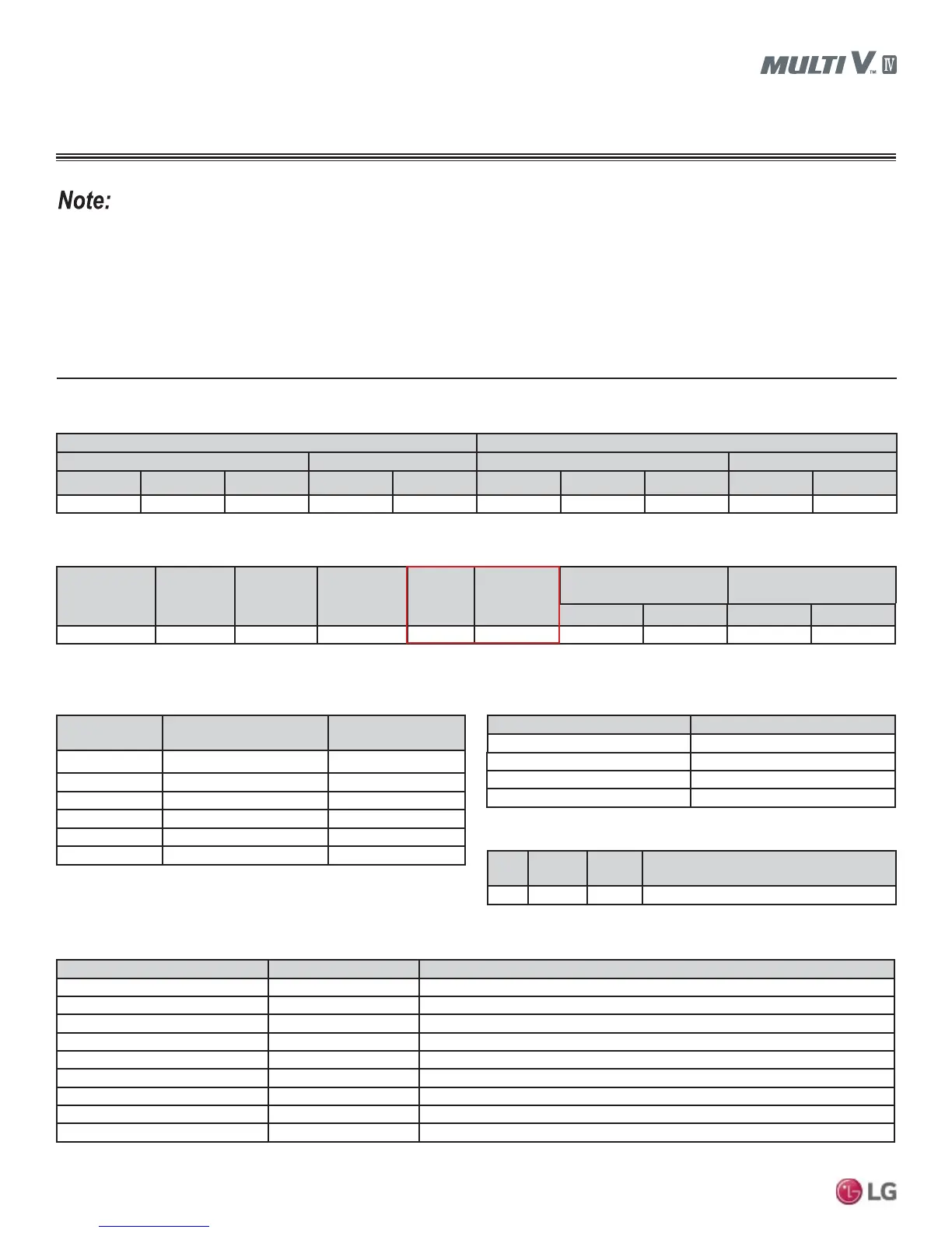
/$76&DOFXODWHG5HIULJHUDQW&KDUJH([DPSOH
LG Multi V IV outdoor units ship from the factory with a charge of R410A refrigerant. This charge serves as the base charge and will not be
sufficient for the system to operate. A trim charge will need to be added after the system is installed that is based on system design. LATS
Multi V piping design software will calculate the size of the refrigerant piping and calculate the refrigerant charge; this added trim refrigerant
charge is shown on the LATS Multi V output.
The example LATS Multi V design software report below shows both the base charge and the calculated trim charge (Tables 43-48). The
information used in the tables below are obtained from a LATS-generated report.
Consider refrigerant safety in all designs.
Project Name: Multi V IV Heat Recovery System Test Update System No: 1/1
Table 43: Design Conditions.
Summer Winter
Indoor Outdoor Indoor Outdoor
DB (°F) WB (°F) RH (%) DB (°F) WB (°F) DB (°F) WB (°F) RH (%) DB (°F) WB (°F)
80.6 67.1 50 93.9 73.9 68.0 56.8 50 17.1 16.2
Table 44:2XWGRRU8QLW6SHFL¿FDWLRQV
Model Name
Max. Indoor
Unit
Connectivity
Max. Total
Over Load
(kBtu/h/%)
Indoor Unit to
Outdoor Unit
Ratio
Product
Charge
1
(lbs.)
Additional
Ref. Amount
2
(lbs.)
Rated / Corrected Capacity
(kBtu/h)
Rated / Corrected
Power Input (kW)
Cooling Heating Cooling Heating
ARUB121DTE4 20 156.0 (130%) 1.26:1 23.6 18.26 120.0 / 126.0 135.0 / 127.8 8.5 / 9.2 8.7 / 10.6
Table 45:3LSLQJ6SHFL¿FDWLRQV
Index (from
LATS selection)
Piping Dia. (Inches)
Liquid : Vapor
Length (Feet)
1
P28 1/2 : 3/4 : 1+1/8 20.0
P22 3/8 : 3/4 : 7/8 15.0
P0 1/4 : 1/2 130.0
P1 3/8 : 5/8 50.0
P27 3/8 : 5/8 : 3/4 35.0
P21 3/8 : 1/2 : 5/8 16.0
Table 46: Branches / Headers / Common Pipes / Heat Recovery Units.
Model Name Quantity
ARBLB03321 1
PRHR042A 1
PRHR032A 1
PRHR022A 1
1
It is imperative to know the “as-built” physical length of each segment of liquid line, to calculate the
total refrigerant charge required. An accurate “as built” field-verified piping diagram is required to verify
within LATS that piping is within limits, proper pipe sizing, and refrigerant charge.
Table 47: Accessories.
Model Name Quantity Description
ARNU183SCL4 1 Wall Mounted (18 MBh)
ARNU183TQC4 1 Ceiling Cassette - Four-Way (18 MBh)
ARNU243BGA4 1 Ceiling-Concealed Ducted - High Static (24 MBh)
ARNU123SBL4 2 Wall Mounted (12 MBh)
ARNU123SER2 1 Art Cool Mirror (12 MBh)
ARNU183NJA4 1 Vertical / Horizontal Air Handling Unit (18 MBh)
ARNU123VEA2 1 Convertible Surface (12 MBh)
ARNU183CFU4 1 Floor Standing - Without Case (18 MBh)
Total 9 -
Table 48: Indoor Units.
Index
Model
Name
Quantity Description
IDU PT-UMC 1 Std. Grille - Four-way Cassette (TN, TM, TP)
1
Product Charge = Factory charge of outdoor unit.
2
Additional Ref Amount = Trim charge.
REFRIGERANT PIPING DESIGN