'XHWRRXUSROLF\RIFRQWLQXRXVSURGXFWLQQRYDWLRQVRPHVSHFL¿FDWLRQVPD\FKDQJHZLWKRXWQRWL¿FDWLRQ
©
/*(OHFWURQLFV86$,QF(QJOHZRRG&OLIIV1-$OOULJKWVUHVHUYHG³/*´LVDUHJLVWHUHGWUDGHPDUNRI/*&RUS
126 |5()5,*(5$17'(6,*1
MULTI V IV Outdoor Unit Engineering Manual
REFRIGERANT PIPING DESIGN
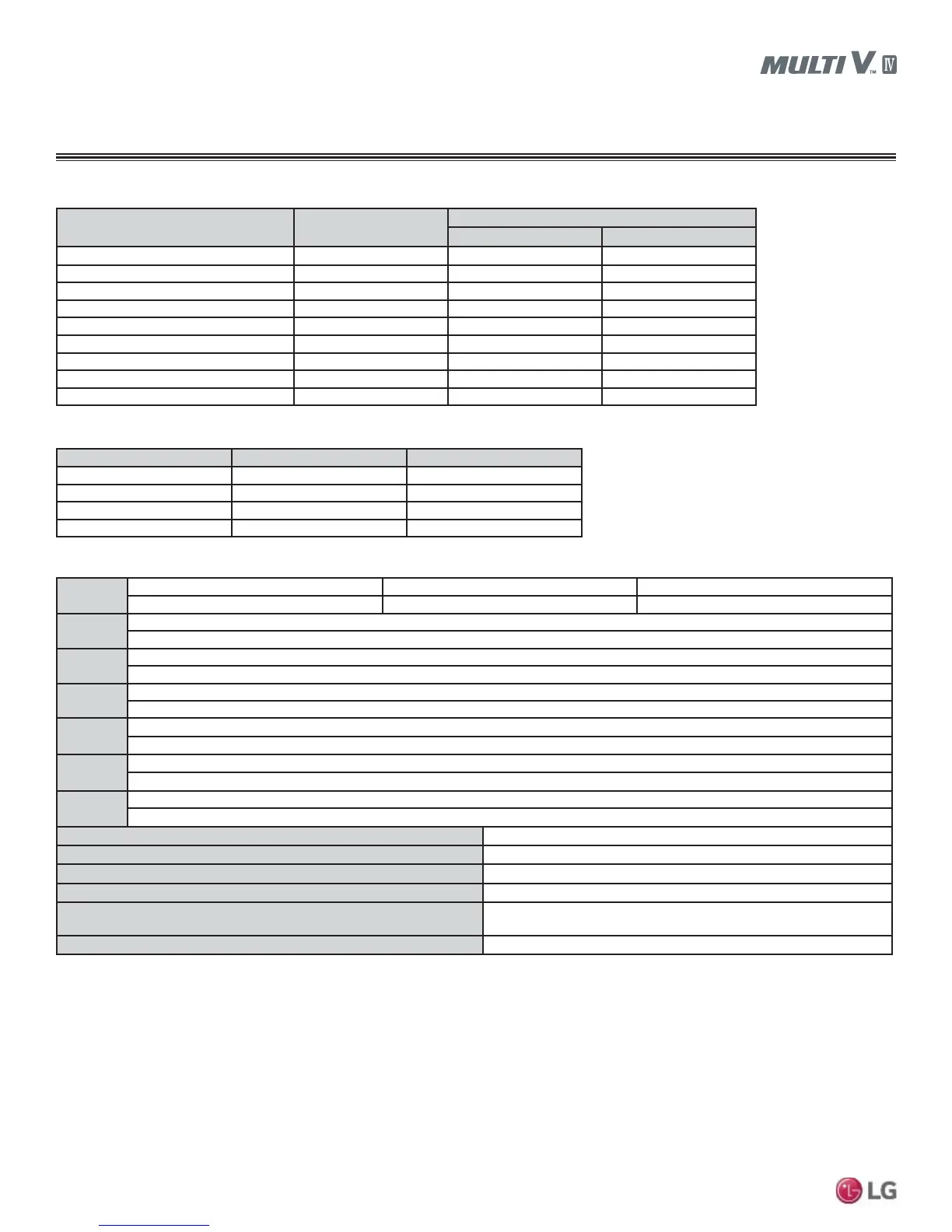
Piping Design Guideline Summary
Downstream IDU total capacity (Btu/h) Liquid pipe (inches OD)
Vapor pipe (inches OD)
Low pressure High pressure
1/4Ø 1/2Ø 3/8Ø
<54,600 3/8Ø 5/8Ø 1/2Ø
<76,400 3/8Ø 3/4Ø 5/8Ø
<114,700 3/8Ø 7/8Ø 3/4Ø
<172,000 1/2Ø 1-1/8Ø 7/8Ø
<229,400 5/8Ø 1-1/8Ø 7/8Ø
<248.500 5/8Ø 1-3/8Ø 1-1/8Ø
<344,000 3/4Ø 1-3/8Ø 1-1/8Ø
<592,500 3/4Ø 1-5/8Ø 1-3/8Ø
Length
Total pipe length Longest actual pipe length Equivalent pipe length
1
$Ȉ%Ȉ&IHHW IHHWIHHWFRQGLWLRQDODSSOLFDWLRQ IHHWIHHWFRQGLWLRQDODSSOLFDWLRQ
Ɛ
Longest pipe length after first branch
IHHWIHHWFRQGLWLRQDODSSOLFDWLRQ
Elevation1
(OHYDWLRQGLIIHUHQWLDO2XWGRRU8QLWļ,QGRRU8QLW
+HLJKWIHHW
Elevation2
(OHYDWLRQGLIIHUHQWLDO,QGRRU8QLWļ,QGRRU8QLW
KHLJKWIHHW
Elevation3
(OHYDWLRQGLIIHUHQWLDO,QGRRU8QLWļ+HDW5HFRYHU\8QLW>VLQJOHKHDWUHFRYHU\XQLWRUVHULHVKHDWUHFRYHU\XQLWV@
49 feet
Elevation4
(OHYDWLRQGLIIHUHQWLDO,QGRRU8QLWļ,QGRRU8QLW>FRQQHFWHGWRVDPH+HDW5HFRYHU\8QLW@
49 feet
height1
(OHYDWLRQGLIIHUHQWLDO2XWGRRU8QLWļ2XWGRRU8QLW
IHHW
Distance between Outdoor Unit to Outdoor Unit
IHHW0D[IHHWIRU2XWGRRU8QLWWRQV
'LVWDQFHEHWZHHQ¿WWLQJVDQG,QGRRU8QLW
LQFKHV
'LVWDQFHEHWZHHQ¿WWLQJVDQG<EUDQFKHV+HDGHUV
LQFKHV
Distance between two Y-branches / Headers
LQFKHV
Height differential between two Heat Recovery Units if installed with a
Y-branch
IHHW
Height differential between two series-piped Heat Recovery Units
IHHW
Table 40: Refrigerant Pipe (B) Diameter between Y-branches and Y-branches / Heat Recovery Unit / Headers.
Table 41: Indoor Unit Connecting Pipe from Branch (C).
1
For calculation purposes, assume equivalent pipe length of Y-branches to be 1.6 feet, and the equivalent pipe length of headers to be 3.3 feet.
Conditional Applications
Conditional application is computed in LATS. See below for an explanation of when pipes are upsized.
,IWKHHTXLYDOHQWOHQJWKEHWZHHQWKH¿UVW<EUDQFKWRWKHIDUWKHVWLQGRRUXQLWLV!IHHWPD[LPXPIHHW
• Pipe segment diameters between the first branch and the last branch should be sized up by one. This applies to both liquid and low / high
vapor pipes. If the next size up is not available, or if the pipe segment diameters are the same as main pipe (A) diameters, sizing up is not
possible.
• :KLOHFDOFXODWLQJWRWDOUHIULJHUDQWSLSLQJOHQJWKSLSH%VHJPHQWOHQJWKVEHWZHHQWKH¿UVW<EUDQFKDQGVHFRQG<EUDQFKDQGEHWZHHQWKHVHFRQG
Y-branch and the heat recovery unit should be calculated by two.
• /HQJWKRISLSH&IURPHDFKLQGRRUXQLWWRWKHFORVHVW<EUDQFKKHDGHURUKHDWUHFRYHU\XQLWIHHW
• >/HQJWKRISLSHIURPRXWGRRUXQLWWRIDUWKHVWLQGRRUXQLW$%&@>/HQJWKRISLSHIURPRXWGRRUXQLWWRFORVHVWLQGRRUXQLW$%&@IHHW
Table 42: Pipe Capabilities.
Indoor Unit Capacity
1
Liquid pipe (inches OD) Vapor pipe (inches OD)
1/4Ø 1/2Ø
3/8Ø 5/8Ø
3/8Ø 3/4Ø
3/8Ø 7/8Ø
1
9,600-24,200 Btu/h 4-way 3 feet x 3 feet Cassette and 15,400-24,200 Btu/h High Static Ducted IDUs have 3/8Ø (liquid) and 5/8Ø (vapor).
The following is an example of manual pipe size calculations. Designers are highly encouraged to use LATS instead of manual calculations.