PRODUCT DATA | 19
Product Data
'XHWRRXUSROLF\RIFRQWLQXRXVSURGXFWLQQRYDWLRQVRPHVSHFL¿FDWLRQVPD\FKDQJHZLWKRXWQRWL¿FDWLRQ
©
/*(OHFWURQLFV86$,QF(QJOHZRRG&OLIIV1-$OOULJKWVUHVHUYHG³/*´LVDUHJLVWHUHGWUDGHPDUNRI/*&RUS
GENERAL DATA
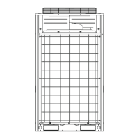
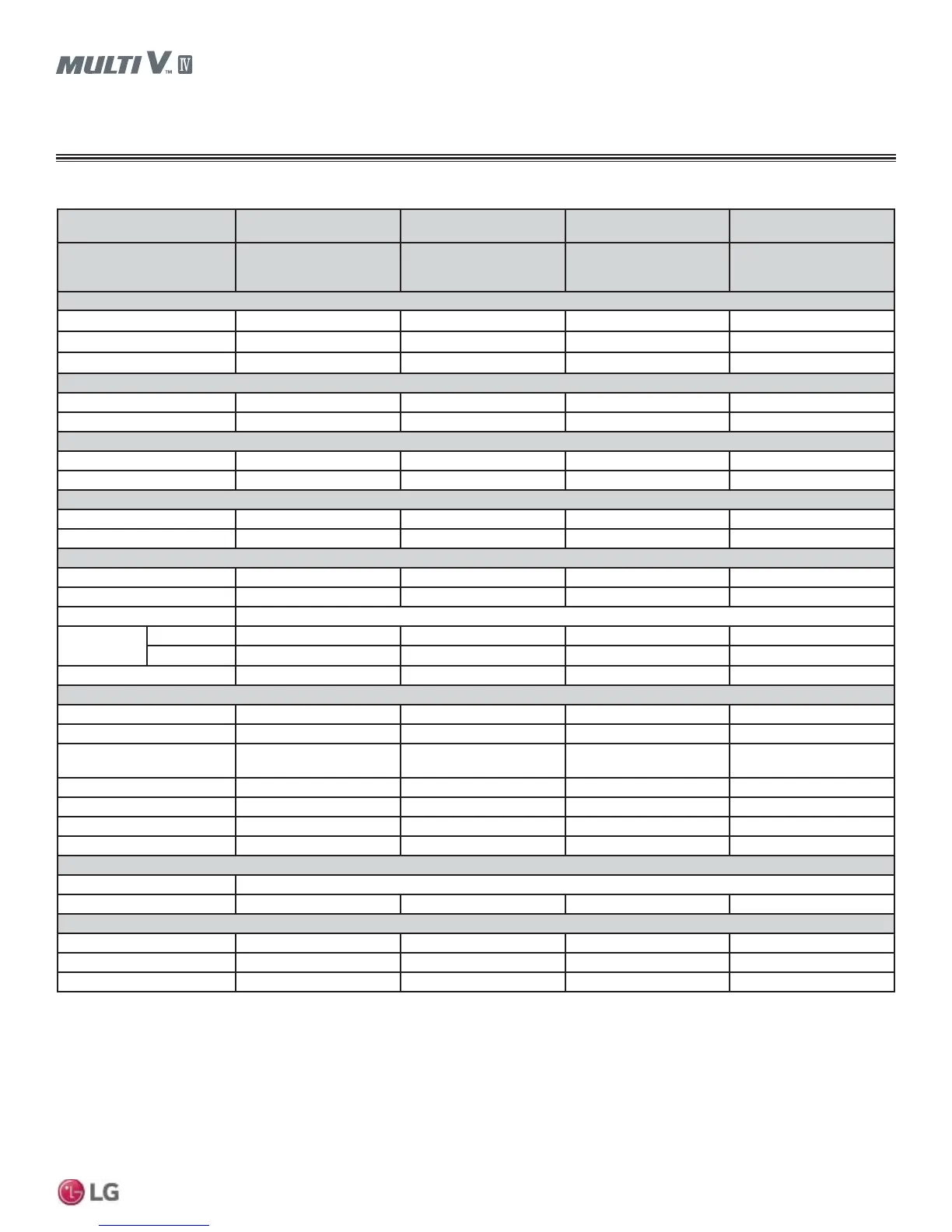
$5816HULHV+HDW3XPS2XWGRRU8QLW6SHFL¿FDWLRQV
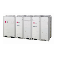
Table 10: Triple-Frame 460V Heat Pump Units, continued.
Combination Unit Model
Number
36.0 Ton
ARUN432DTE4
38.0 Ton
ARUN456DTE4
40.0 Ton
ARUN480DTE4
42.0 Ton
ARUN504DTE4
Individual Component Model
Numbers
1
ARUN145DTE4 +
ARUN145DTE4 +
ARUN145DTE4
ARUN145DTE4 +
ARUN145DTE4 +
ARUN169DTE4
ARUN145DTE4 +
ARUN169DTE4 +
ARUN169DTE4
ARUN169DTE4 +
ARUN169DTE4 +
ARUN169DTE4
Cooling Performance
Nominal Cooling Cap. (Btu/h)
2
432,000 456,000 480,000 504,000
Rated Cooling Cap. (Btu/h)
3
414,000 436,000 458,000 479,000
Max. Nominal Cooling Cap.
4
561,600 592,800 624,000 655,200
Heating Performance
Nominal Heating Cap. (Btu/h)
2
486,000 513,000 540,000 567,000
Rated Heating Cap. (Btu/h)
3
462,000 488,000 514,000 539,000
Operating Range
Cooling (°F DB)
4
14 to 122 14 to 122 14 to 122 14 to 122
Heating (°F WB)
-13 to +61 -13 to +61 -13 to +61 -13 to +61
Compressor
Inverter Quantity
HSS DC Scroll x 6 HSS DC Scroll x 6 HSS DC Scroll x 6 HSS DC Scroll x 6
Oil/Type
PVE/FVC68D PVE/FVC68D PVE/FVC68D PVE/FVC68D
Fan (Top Discharge)
Type
Propeller (BLDC) Propeller (BLDC) Propeller (BLDC) Propeller (BLDC)
Motor Output (kW) x Qty.
0.60 x 2 + 0.60 x 2 + 0.60 x 2 0.60 x 2 + 0.60 x 2 + 0.60 x 2 0.60 x 2 + 0.60 x 2 + 0.60 x 2 0.60 x 2 + 0.60 x 2 + 0.60 x 2
Motor/Drive
Brushless Digitally Controlled/Direct
Operating
Range (RPM)
Cooling
0 - 1,100 0 - 1,100 0 - 1,100 0 - 1,100
Heating
80 - 1,100 80 - 1,100 80 - 1,100 80 - 1,100
Maximum Air Volume (CFM)
30,600 30,600 30,600 30,600
Unit Data
Refrigerant Type
R410A R410A R410A R410A
Refrigerant Control/Location
EEV/Indoor Unit EEV/Indoor Unit EEV/Indoor Unit EEV/Indoor Unit
Min. to Max. No. Indoor Units/
System
5
1 - 64 1 - 64 1 - 64 1 - 64
Sound Pressure dB(A)
6
64.3 64.3 64.3 64.3
Net Unit Weight (lbs.)
672 + 672 + 672 672 + 672 + 672 672 + 672 + 672 672 + 672 + 672
Shipping Weight (lbs.)
705 + 705 + 705 705 + 705 + 705 705 + 705 + 705 705 + 705 + 705
Communication Cables
7,8
2 x 18 2 x 18 2 x 18 2 x 18
Heat Exchanger
Material and Fin Coating
Copper Tube/Aluminum Fin and GoldFin™/Hydrophilic
Rows/Fins per inch
3/14 3/14 3/14 3/14
Piping
9
Liquid Line Conn. (in., OD)
5/8 + 5/8 + 5/8 Braze 5/8 + 5/8 + 5/8 Braze 5/8 + 5/8 + 5/8 Braze 5/8 + 5/8 + 5/8 Braze
Vapor Line Conn (in., OD)
1-1/8 + 1-1/8 + 1-1/8 Braze 1-1/8 + 1-1/8 + 1-1/8 Braze 1-1/8 + 1-1/8 + 1-1/8 Braze 1-1/8 + 1-1/8 + 1-1/8 Braze
Factory Charge lbs. of R410A
23.6 + 23.6 + 23.6 23.6 + 23.6 + 23.6 23.6 + 23.6 + 23.6 23.6 + 23.6 + 23.6
1
ARUN145BTE4/ARUN145DTE4, ARUN169BTE4/ARUN169DTE4 frames are ONLY for use in large
capacity triple frame combinations. They cannot be used as stand alone models or in a dual frame
combination. These frames ARE NOT interchangeable with ARUN144BTE4/ARUN144DTE4, ARUN-
168BTE4/ARUN168DTE4 single frame models.
2
Nominal capacity applied with non-ducted indoor units, and is rated 0 ft. above sea level with 25 ft.
of refrigerant line per indoor unit and a 0 ft. level difference between outdoor and indoor units. All
capacities are net with a Combination Ratio between 95–105%.
Nominal cooling capacity rating obtained with air entering the indoor unit at 80ºF dry bulb (DB) and 67ºF
wet bulb (WB) and outdoor ambient conditions of 95ºF dry bulb (DB) and 75ºF wet bulb (WB).
Nominal heating capacity rating obtained with air entering the indoor unit at 70ºF dry bulb (DB) and
59ºF wet bulb (WB) and outdoor ambient conditions of 47ºF dry bulb (DB) and 43ºF wet bulb (WB).
3
Rated capacity is certified under AHRI Standard 1230. See www.ahrinet.org for information.
4
Cooling range with Low Ambient Baffle Kit (sold separately) is -9.9°F to +122°F.
5
The System Combination Ratio must be between 50–130%.
6
Sound pressure levels are tested in an anechoic chamber under ISO Standard 3745.
7
All communication cable to be minimum 18 AWG, 2-conductor, stranded, shielded, and must comply
with applicable local and national codes. Ensure the communication cable is properly grounded at the
master unit only. Do not ground the ODU-IDU communication cable at any other point.
8
Power wiring cable is field provided and must comply with the applicable local and national codes. See
page 32 for detailed electrical data.
9
Refer to the Refrigerant Piping section of this manual for correct line sizing. Contractor must use LG
manufactured Y-Branch and Header Kits only. Designer must verify refrigerant piping design configura-
tion using LG’s computerized refrigerant piping (LATS Multi V) software to validate the pipe design.