88 | PRODUCT DATA
MULTI V IV Outdoor Unit Engineering Manual
'XHWRRXUSROLF\RIFRQWLQXRXVSURGXFWLQQRYDWLRQVRPHVSHFL¿FDWLRQVPD\FKDQJHZLWKRXWQRWL¿FDWLRQ
©
/*(OHFWURQLFV86$,QF(QJOHZRRG&OLIIV1-$OOULJKWVUHVHUYHG³/*´LVDUHJLVWHUHGWUDGHPDUNRI/*&RUS
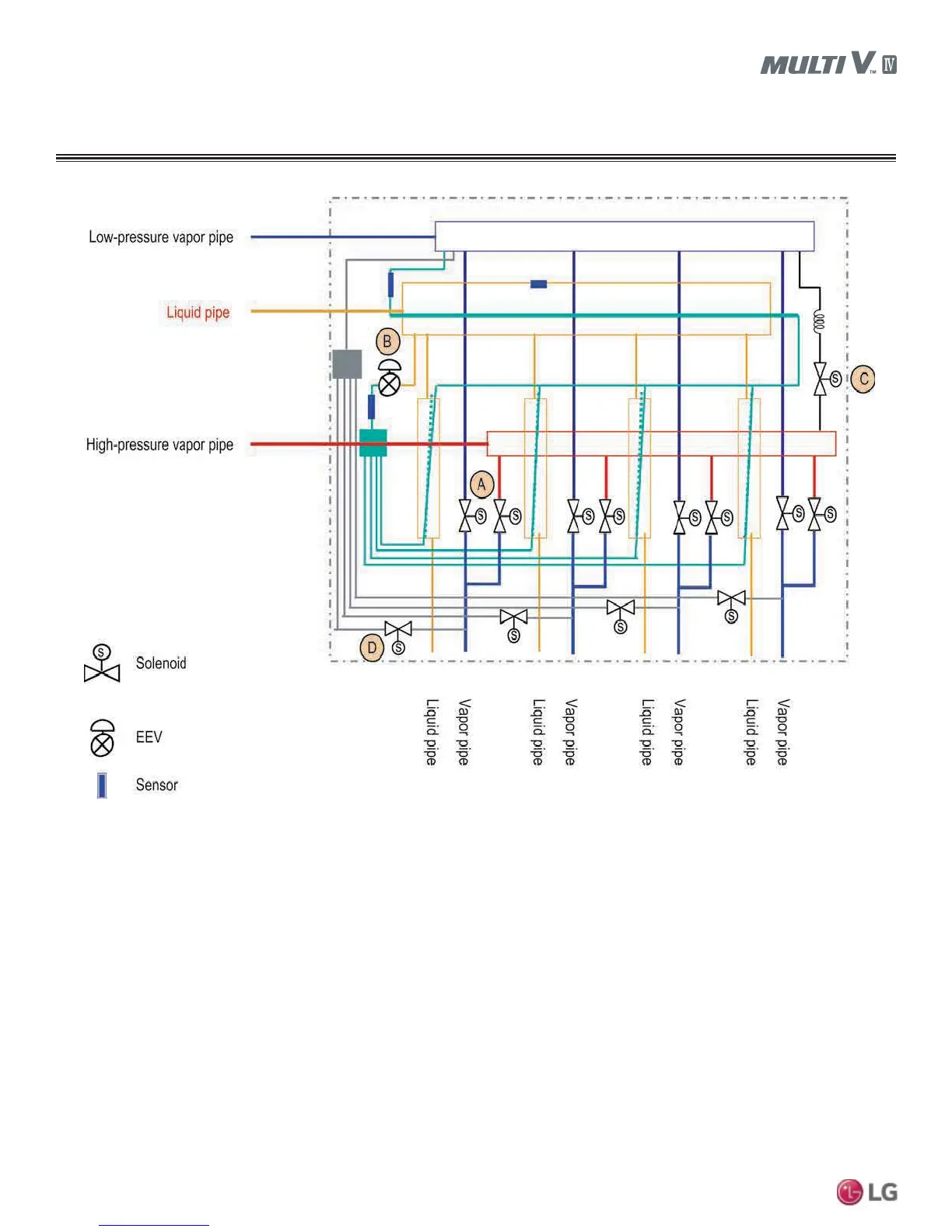
REFRIGERANT FLOW DIAGRAMS
A : Switch operation between cooling and heating.
B : Decreases noise following subcooling operation between inlet of one indoor unit and outlet of another indoor unit during simultaneous
operation.
C : Prevents liquid from entering high-pressure vapor valve and heat recovery unit during cooling mode.
D : Controls pressure between the high and low pressure vapor pipes during simultaneous operation.
35+5$35+5$35+5$+HDW5HFRYHU\8QLWV