4 Chapter 1 Overview
Liebert NXC 30kVA And 40kVA UPS User Manual
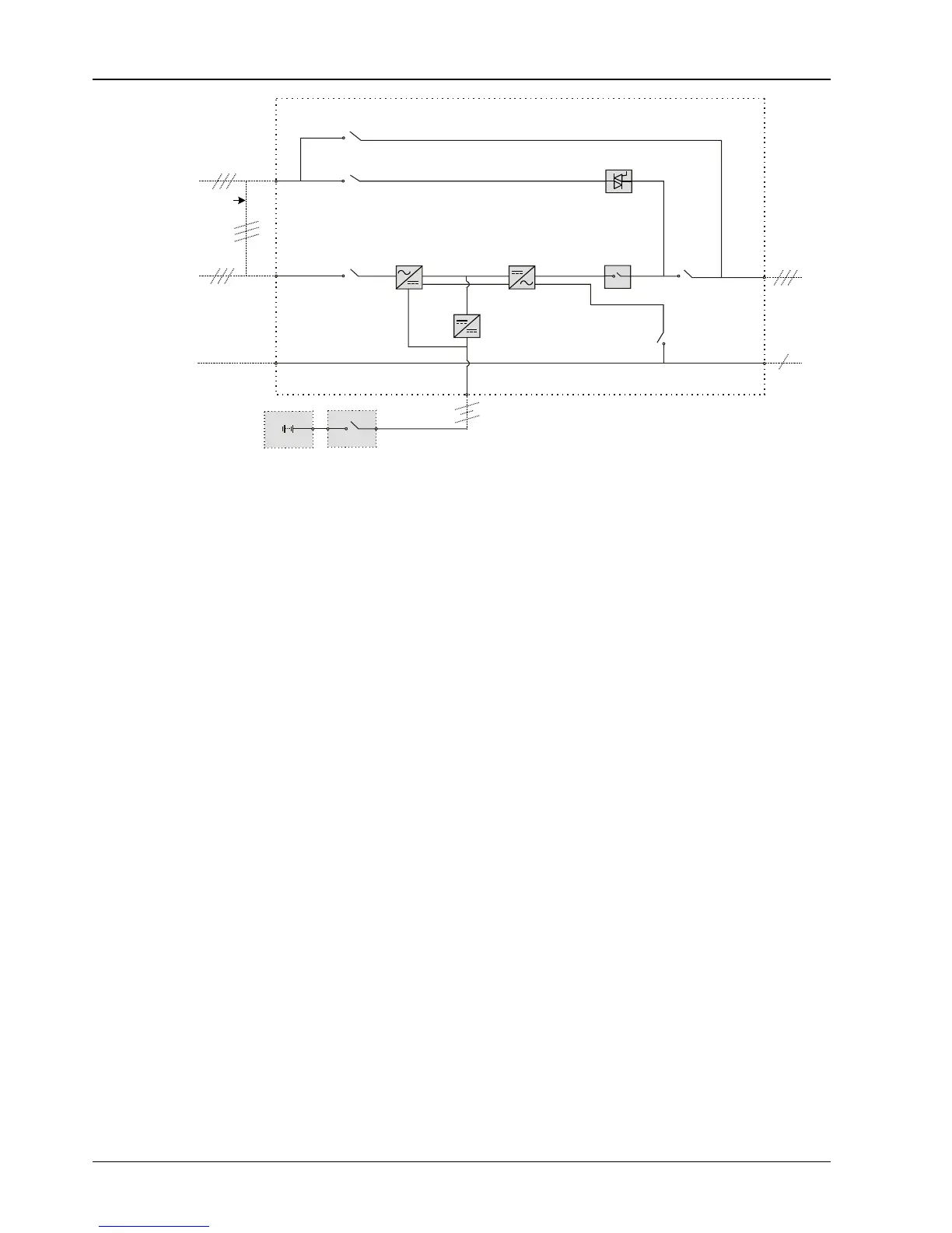
Figure 1-2 UPS power supply switch configuration
1.2.5 Battery Circuit Breaker (BCB)
The external battery shall be connected to the UPS through the BCB. The BCB box is a standard option, which shall
be installed near the battery. The BCB is closed manually or electrically. The BCB has undervoltage tripping coil. Upon
the DC bus undervoltage, the UPS control circuit will send a signal to the coil to trip the BCB. It also has a magnetic trip
facility for overload protection.
1.3 Parallel System
Up to four UPS modules can be parallel-connected to form a parallel system to increase the system capacity or
reliability, or both. The load is equally shared between the paralleled UPS modules.
Moreover, two UPS modules or parallel system can comprise a dual bus system (LBS). Each UPS module or parallel
system has independent output. Output synchronization is achieved through the LBS cable, thus enabling seamless
load transfer between the two systems.
1.3.1 Parallel System Features
1. The hardware and software of parallel system are completely the same as those of the single module. The parallel
system configuration is achieved through settings in configuration software or panel buttons.
2. Parallel cables are connected in a ring, providing both system reliability and redundancy. LBS cables are connected
between any two UPS modules of each bus. The intelligent parallel logic provides the user with maximum flexibility.
For example, shutting down or starting up UPS modules in a parallel system can be done in any sequence. Transfers
between normal mode and bypass mode of operation are seamless and self-recoverable, that is, the overload is
cleared, and the system will be automatically recovered to its original operation mode.
3. The total load of the parallel system can be queried from each UPS module’s LCD.
1.3.2 Parallel System Requirements
A group of paralleled modules behave as if it were one large UPS with the advantage of presenting higher reliability. To
ensure that all modules are equally utilised and to comply with relevant wiring rules, the following requirements apply:
1. All UPS modules must be of the same rating and must be connected to the same bypass source.
2. The bypass and rectifier input sources must be connected to the same neutral line input terminal.
3. Any RCD, if installed, must be of an appropriate setting and located upstream of the common neutral line input
terminal. Alternatively, the device must monitor the protective earth current of the system. Refer to Warning: high earth
leakage current before Contents.