Chapter 3 Electrical Installation 15
Liebert NXC 30kVA And 40kVA UPS User Manual
Chapter 3 Electrical Installation
This chapter mainly introduces the electrical installation of the UPS, including the power cable and signal cable
connecting procedures and methods.
After completing the mechanical installation of the UPS, it is required to connect the power cable and signal cable of
the UPS. All the signal cables, whether shielded or not, shall be kept away from the power cables.
Warning
1. Do not power on the UPS before the arrival of authorized service engineer.
2. The UPS cables should be routed by an authorized engineer in accordance with the information contained in this chapter.
3.1 Wiring Of Power Cable
3.1.1 System Configuration
The cable size of the system power cable shall meet the following requirements:
UPS input cable
The cable size of the UPS input cable differs with the UPS power ratings and input AC voltages, provided that it meets
the requirement of maximum input current, including the maximum battery charge current, see Table 3-1.
UPS bypass and output cable
The cable size of the UPS bypass and output cable differs with the UPS power rating and output AC voltages,
provided that it meets the requirement of nominal output or bypass current, as shown in Table 3-1.
Battery cable
Each UPS connects to its battery through the three cables connecting to the positive pole, negative pole and neutral
line. The cable size of the battery cable differs with the UPS power ratings, provided that it meets the battery discharge
current requirement when the battery discharges to near EOD voltage, as shown in Table 3-1.
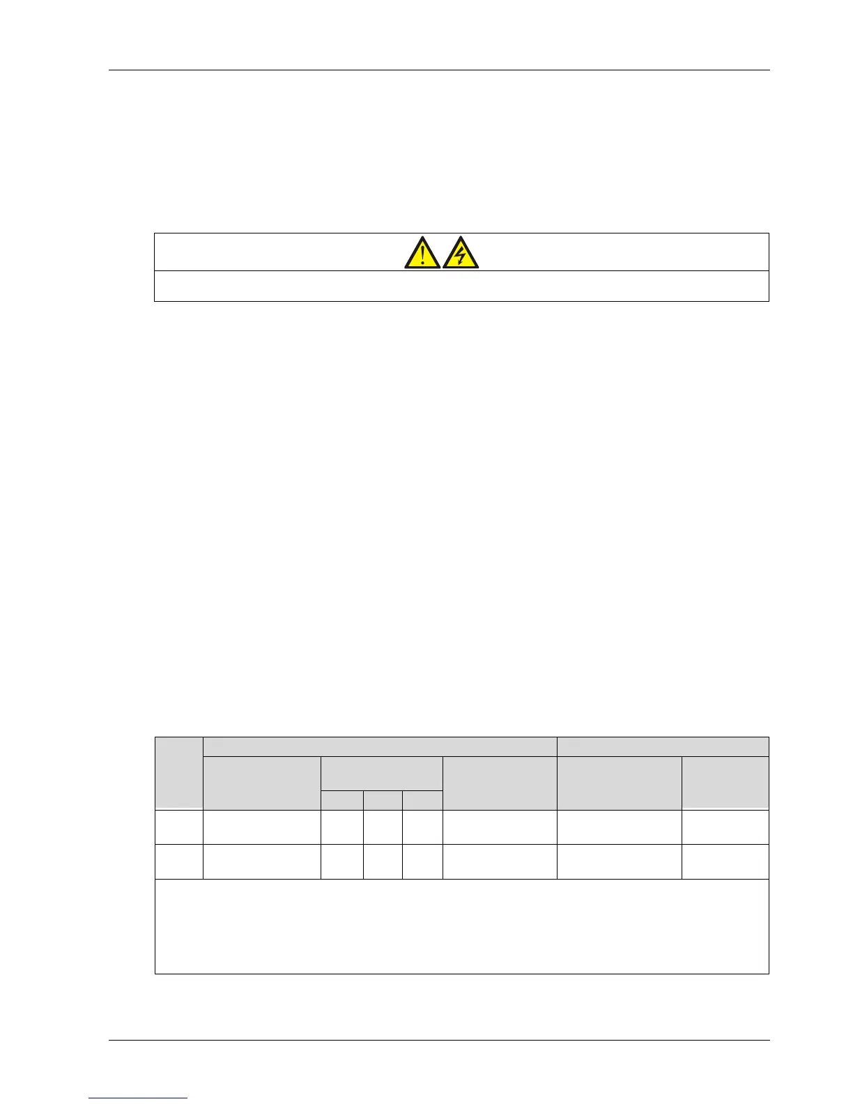
3.1.2 Maximum Steady State AC And DC Currents
The power cable must be selected according to the current and voltage values in Table 3-1 as well as the local wiring
regulations, and take environmental conditions (temperature and physical media) into consideration, then refer to
Table 3B in IEC 60950-1.
Table 3-1 Max. steady state AC and DC currents
UPS
power
(kVA)