64 Chapter 8 Options
Liebert NXC 30kVA And 40kVA UPS User Manual
Chapter 8 Options
This chapter provides the UPS option list, and introduces the functions, installation and configuration of each option.
8.1 Option List
See Table 8-1 for option list of the UPS.
Table 8-1 Option list
Bypass load sharing inductor kit
Common for 30kVA and 40kVA
Or select the battery cable and battery tray, battery string is user-prepared
Battery temperature compensation kit
Used together with UF-RS485 card
Common for 30kVA and 40kVA
Intellislot ports 1 ~ 3 (Intellislot port 2 recommended)
Intellislot ports 1 and 3 (Intellislot port 1 recommended)
Intellislot ports 1 and 3 (Intellislot port 3 recommended)
Used to connect and control the external battery string
Available in 5m, 10m, 15m
Available in 5m, 10m, 15m
8.2 Opertion Introduction
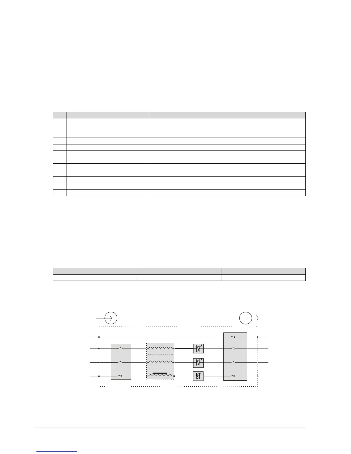
8.2.1 Bypass Load Sharing Inductor Kit
Install the bypass load sharing inductors for the parallel system comprised of two or more UPS modules, to ensure the
bypass output load sharing for the parallel system. The bypass load sharing inductor is used to compensate the
impedance differentia between SCR and cable. See Table 8-2 for the specifications.
Table 8-2 Specifications of bypass load sharing inductor
Dimensions (H × W × D) (mm)
Each UPS cabinet has three bypass load sharing inductors, with no extra clearance occupied. The load sharing rate is
generally 10% of the system rated current with the difference of external cable configuration. Try to make the cable
length be the same from bypass to each UPS and from UPS module output to parallel system connection point.
Figure 8-1 Operation principle of bypass load sharing inductor
Preparation
1. Prepare the installation tools, including a cross head screwdriver, a pair of diagonal cutting pliers, a sleeve and an
adjustable spanner.
Input
N
U3
V3
W3
Q2
Q5
Bypass load sharing inductor
Static switch
UPS1
Output
N2
U2
V2
W2