16 Chapter 3 Electrical Installation
Liebert NXC 30kVA And 40kVA UPS User Manual
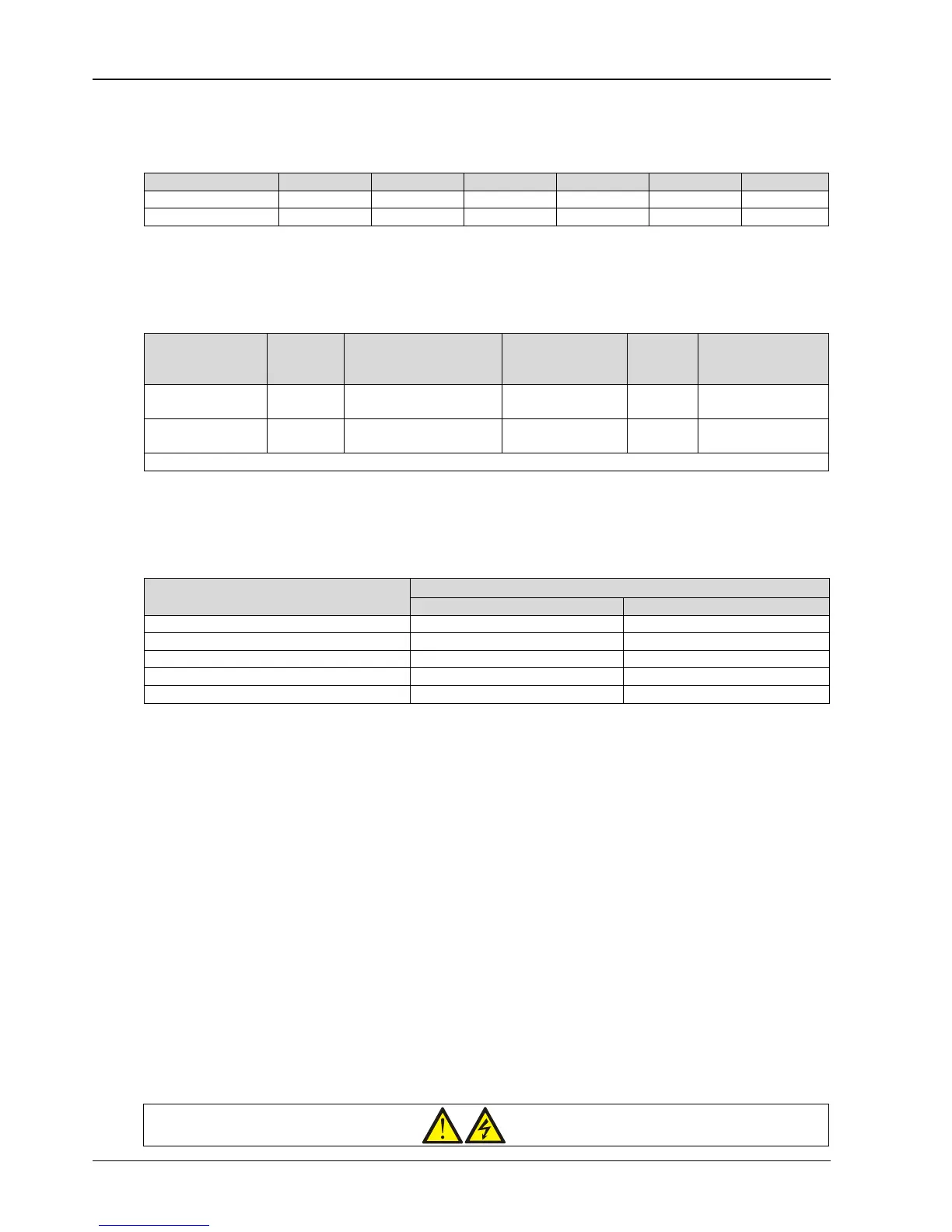
3.1.3 CSA Of UPS Cable
The minimum CSA of the UPS cable is listed in Table 3-2.
Table 3-2 Min. CSA of the UPS cable (unit: mm
2
, ambient temperature: 25°C)
3.1.4 Selection Of UPS I/O Switch
Table 3-3 is the recommended UPS I/O switch capacity, and the user can select it according to actual needs.
Table 3-3 Selection of the UPS I/O switch
Model Input port
Recommended capacity
of input external switch
BCB
Output
port
block
100A (3P)
Note: The BCB (125A) is recommended for common input configuration
3.1.5 Distance Between The UPS Connection Point And The Floor
See Table 3-4 for details.
Table 3-4 Min. distance between UPS connection point and floor
UPS connection point
Min. distance
Rectifier input 345 345
Bypass input 284 284
AC Output 250 250
Battery 994 994
PE terminal 740 740
3.1.6 Notes
The following points are for general guidance only. If there are relevant local regulations, the local regulations shall
prevail.
1. The cable size of the neutral line shall be selected according to 1.5 times of the output/bypass phase current.
2. The cable size of the protective earth cable shall be selected according to the AC power failure level, cable length
and protection type. The grounding wire connection must use the shortest connection route.
3. For the cables with large current, parallel connection of small cables can be adopted to facilitate the installation.
4. When selecting the battery cable size, the current value in Table 3-1 shall be referred to, and a maximum voltage
drop of 4Vdc is allowed.
5. Do not form coils, so as to minimize the formation of EMI.
3.1.7 Power Cable Connecting Terminal
The rectifier input, bypass input, output and battery power cables are connected to the corresponding terminals shown
in Figure 3-2. Protection Ground
The protective earth cable is reliably connected to the PE input terminal (see Figure 3-2) via the fixing bolt. All the
cabinets and cable troughs shall be grounded according to the local regulations. The grounding wires shall be tied up
reliably to prevent the loosening of the grounding wire tightening screws when the grounding wires are pulled.
Warning