24 Chapter 3 Electrical Installation
Liebert NXC 30kVA And 40kVA UPS User Manual
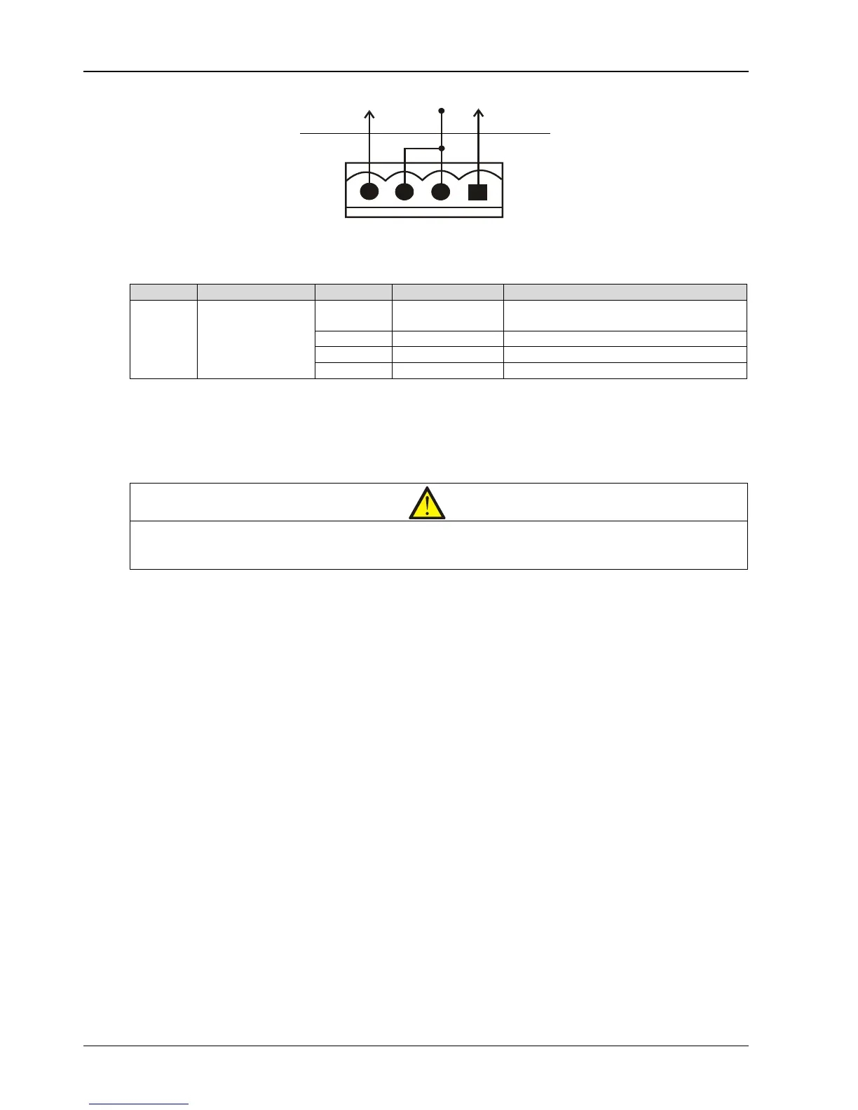
Figure 3-9 Remote EOP input port J3
Table 3-8 Description of remote EPO input port
EPO is triggered when pins 3 and 4 of J3 are shorted or pins 2 and 1 of J3 are opened.
If an external EPO facility is required, pins 1 and 2 or 3 and 4 of J3 are reserved for this function. The external EPO
facility is also connected to the normally open or normally closed remote EPO switch between these two terminals
using shielded cable. If this function is not used, pins 3 and 4 of J23 must be opened and pins 1 and 2 of J3 must be
shorted.
Note
power. To disconnect all power to the UPS, open the external power switch, bypass input switch, output switch and BCB after EPO
is activated.
3.2.6 RS232 Communication Port
See Figure 3-5 for the position of RS232 port. RS232 port monitors and sets parameters through connecting with
computer.
The RS232 port provides serial data and is intended for use by authorized commissioning and service personnel in
UPS commissioning and service.
3.2.7 USB Communication Port
See Figure 3-5 for the position of USB port. This port does not open to the customers, just for UPS engineer
commission and update the corresponding software parameters.
Method: Connect one end of the USB communication cable to the USB port in the communication box, and the other
end to the USB port of the computer.
The USB port provides serial data and is intended for use by authorized commissioning and service personnel in UPS
commissioning and service.
Note: To make the communication normal, do not connect the RS232 port and USB port to the computer at the
same time.
3.2.8 Parallel And LBS Communication Ports
See Figure 3-5 for their positions.
3.2.9 RS485 Communication Port
See Figure 3-5 for its position.