Chapter 6 Battery 53
Liebert NXC 30kVA And 40kVA UPS User Manual
Note: The cable of the X102 BCB port must be routed separately from the power cable. It uses the dual-insulated
shielded cable (the CSA is generally 0.5mm
2
~ 1mm
2
when the wiring distance is 25m ~ 50m length), and the two ends
of the shielding coat must be connected to the enclosure reliably. The separate safety earth must be connected
between the UPS and BCB box.
Caution
If the corresponding functions are not required, just do not connect corresponding ternimals.
6.10 BCB Reference Current And Connection
Table 6-6 provides recommended BCB rated current and battery maximum discharge current at full load. Refer to
Table 3B in IEC60950-1, and select the appropriate cable CSA according to local electrical regulations.
Table 6-6 BCB rated current and battery max. discharge current at full load (recommended)
Item Unit
Maximum battery discharge
current at full load
A 95 127
Reference rated current of BCB
34-bolck
battery
Maximum battery discharge
current at full load
A 88 116
Reference rated current of BCB
Maximum battery discharge
current at full load
A 82 108
Reference rated current of BCB
Maximum battery discharge
current at full load
A 76 101
Reference rated current of BCB
Maximum battery discharge
current at full load
A 72 95
Reference rated current of BCB
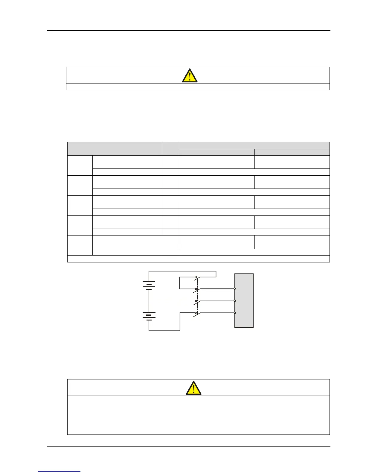
Note: Refer to Figure 6-5 for the connections between the battery, BCB and UPS
Figure 6-5 Connections between the battery, BCB and UPS
6.11 Battery Maintenance
For the battery maintenance and maintenance precautions, refer to IEEE-Std-1188-2005 and the relevant manuals
provided by the battery manufacturer.
Note
1. Periodically check the screws of the battery connection parts and confirm that they are firmly tightened. If there is any loosened
screw, tighten it immediately.
2. Ensure that all safety devices are in place and operate normally, and that the battery management parameters are set properly.
3. Measure and record the air temperature inside the battery room.
4. Check to ensure that the battery terminals have no damage or heat generating trace, and the battery enclosure and terminal
shields are intact.