Chapter 8 Options 71
Liebert NXC 30kVA And 40kVA UPS User Manual
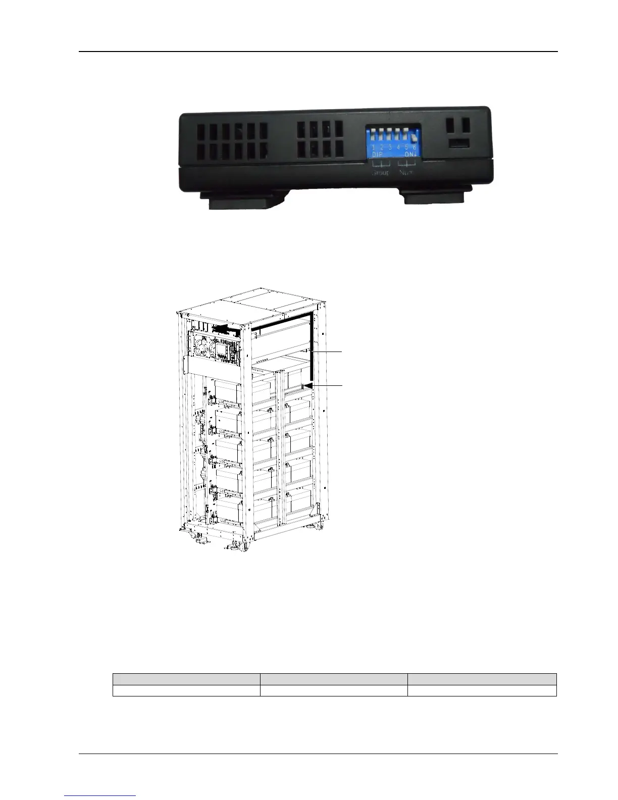
3. According to Figure 8-7, dial the DIP switch 6 (or 5) to ‘ON’, making the lower left corner of the LCD screen of
temperature sensor display 01 (or 02). If two temperature sensors are used together, their DIP switches are not
allowed to be superposition.
Figure 8-7 DIP switch of temperature sensor
4. Remove the right side panel of the cabinet, place the battery temperature sensor onto the back area of the battery
tray 1, and then insert the UF-RS485 card into the Intellislot port 1. The installation method of the UF-RS485 card is
the same as that of the IS-WEBL card described in 8.2.6 IS-WEBL card. Refer to Figure 8-8 for installation and
connection of the battery temperature sensor.
Figure 8-8 Installation and connection of battery temperature sensor
5. Wiring according to Figure 8-8, pack the cables in order. Note that the cables should be routed separately from the
power cables, to avoid EMI.
8.2.4 Seismic Anchor Kit
The UPS provides seismic anchor kits to avoid and reduce the damage to UPS caused by earthquake or vibration.
See Table 8-3 for dimensions of the seismic anchor kits.
Table 8-3 Dimensions of the seismic anchor kits
After fixing the UPS onto the concrete floor, the seismic anchor kits should achieve Class 2 requirement of Table 2 in
IEC60068.3.3 and satisfy the UBC 1994 standard (earthquake area 4 from fierceness to very fierceness).
Installation position of
Route cables along the cabinet column,
battery temperature sensor
and connect them to corresponding terminals