70 Chapter 8 Options
Liebert NXC 30kVA And 40kVA UPS User Manual
Warning
At this moment, the battery voltage over 384V has been input to the UPS cabinet. Insulated gloves and other protective measures
are required.
6. Close the battery compartment door, install the removed fixing screws, then close the UPS front door.
Refer to Chapter 6 Battery for more information of the battery.
8.2.3 Battery Temperature Compensation Kit
A battery temperature sensor is used to measure the battery temperature. The battery temperature is installed next to
the battery for measuring battery temperature. The sensor signal output cable is connected to the UF-RS485 card of
Intellislot 1 port. At this moment, the temperature sensor is connected with the UPS internal logic circuit.
With this feature fitted, the nominal float voltage supplied to the battery is adjusted so as to be inversely proportional to
the ambient temperature of the battery cabinet or battery room. This prevents the battery being over charged at high
ambient temperatures.
Preparation
1. Prepare the installation tools, including a cross head screwdriver.
2. Check that all installation materials are present and complete, including a battery temperature sensor, a UF-RS485
card.
Procedures
Warning
1. Connect the cables strictly following the instructions. Failure to observe this may cause damage to the UPS and the battery.
2. Shut down the UPS when installing the battery temperature sensor. During installation, do not touch the battery terminals,
bared copper bars and components.
1. Shut down the UPS completely.
1) Close the load.
2) Refer to 5.6.1 Procedures For Completely Powering Down UPS for single UPS module shutdown, and 7.3.5
Procedures For Completely Powering Down UPS for parallel system shutdown.
3) All the LCDS are off, wait five minutes for the internal DC bus capacitors of the UPS complete discharging.
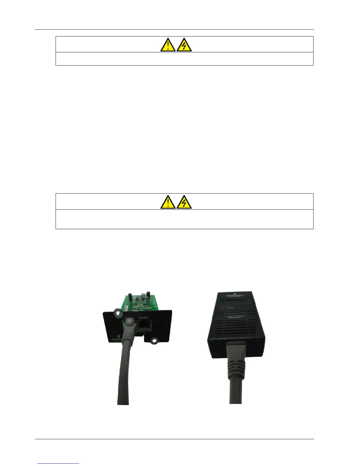
2. Connect one end of the specified cable to either port of the battery temperature sensor, and the other end to each
port of UF-RS485 card. See Figure 8-6.
Figure 8-6 Connection between UF-RS485 card and battery temperature sensor