Chapter 8 Options 65
Liebert NXC 30kVA And 40kVA UPS User Manual
2. Check that all installation materials are present and complete, including three bypass load sharing inductors, 12 M5
× 12 sems screws (for fixing the inductors), six M6 × 16 sems screws (for fixing the power cables), six M6 flat washers
and nuts.
Procedures
Warning
1) Close the load.
2) Refer to 5.6.1 Procedures For Completely Powering Down UPS for UPS module shutdown, and 7.3.5
Procedures For Completely Powering Down UPS for parallel system shutdown.
3) All the LCDS are off, wait five minutes for the internal DC bus capacitors of the UPS complete discharging.
2. Remove the left side panel of the UPS cabinet, reserve the removed screws.
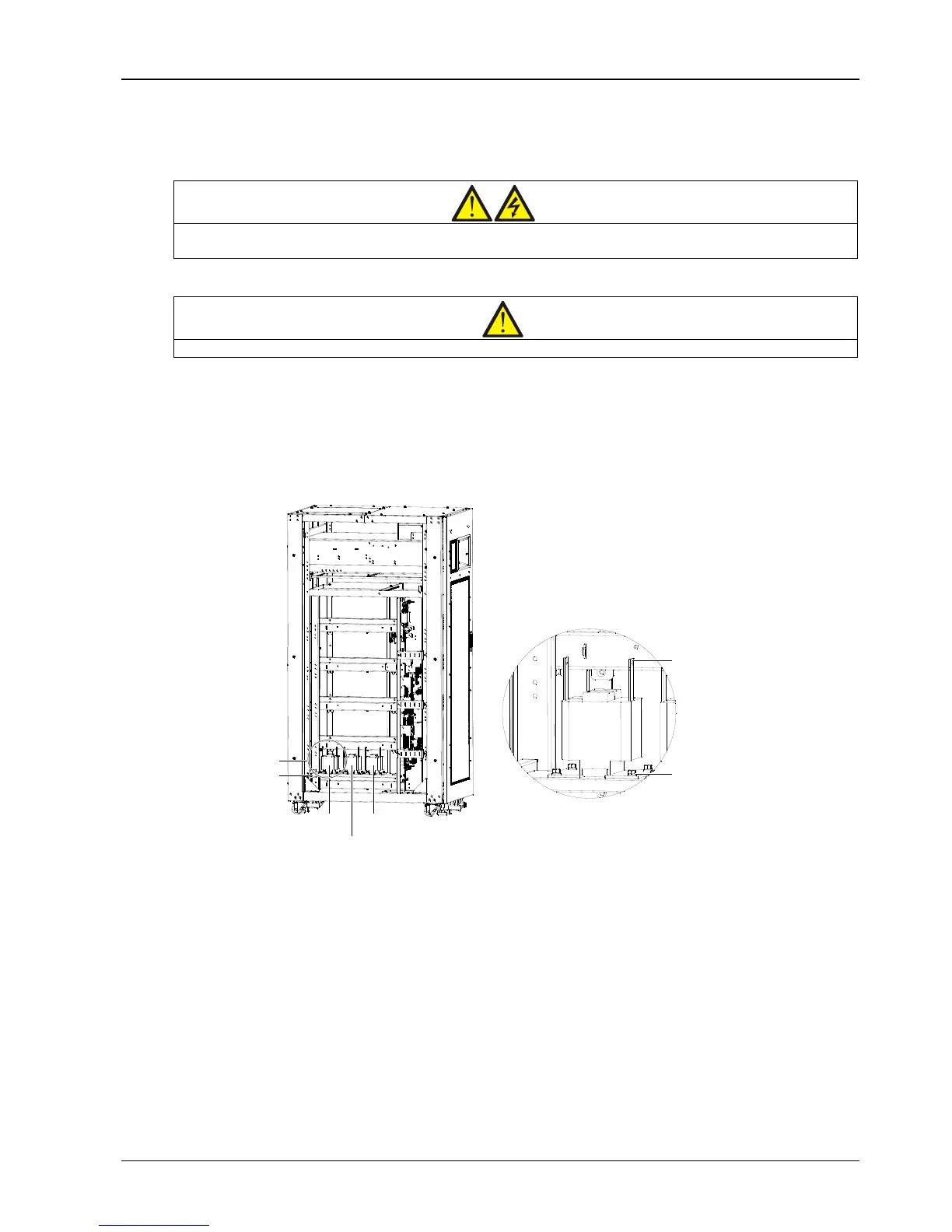
3. Install the three bypass load sharing inductors, see Figure 8-2.
Figure 8-2 Position of bypass load sharing inductors
There are 12 installation holes on the base plate of the UPS cabinet for fixing the three inductors, four installation
holes for each inductor. Place the three inductors in the installation positions shown in Figure 8-2, and fix them on the
base plate of the UPS cabinet with 12 M5 × 12 sems screws.
4. Connection of bypass load sharing inductors.
If the UPS cabinet has been connected three bypass cables (W26, W27, W28), you should first remove the three
cables and follow the procedures below to connect bypass load sharing inductor cables:
1) First respectively connect one end of W62 and W59 to terminal1 and terminal 2 of inductor 1, and use the M6 × 16
sems screws, M6 flat washers and nuts to fasten the terminals. The torque value is 4.8N.m. Then respectively connect
the other end of W62 and W59 to the transfer terminal bC in UPS cabinet and the corresponding cabling hole Q2-6 of
bypass input switch Q2. See Figure 8-3 for details.