66 Chapter 8 Options
Liebert NXC 30kVA And 40kVA UPS User Manual
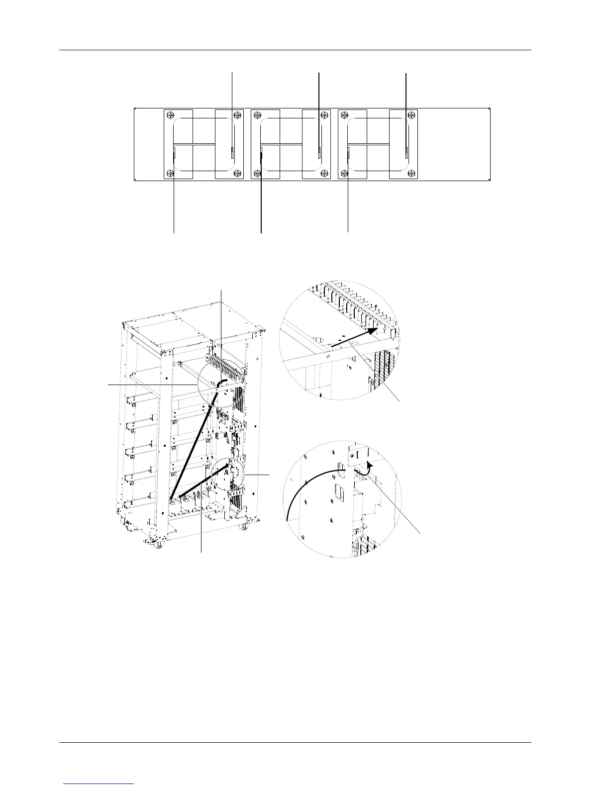
Figure 8-3 Connection of inductor 1
2) Respectively connect one end of W61 and W58 to terminal1 and terminal 2 of inductor 2, and use the M6 × 16 sems
screws, M6 flat washers and nuts to fasten the terminals. The torque value is 4.8N.m. Then respectively connect the
other end of W61 and W58 to the transfer terminal bB in UPS cabinet and the corresponding cabling hole Q2-4 of
bypass input switch Q2. Refer to inductor 1 for the detailed connection method of inductor 2.
3) Respectively connect one end of W60 and W57 to terminal1 and terminal 2 of inductor 3, and use the M6 × 16 sems
screws, M6 flat washers and nuts to fasten the terminals. The torque value is 4.8N.m. Then respectively connect the
other end of W60 and W57 to the transfer terminal bA in UPS cabinet and the corresponding cabling hole Q2-2 of
bypass input switch Q2. Refer to inductor 1 for the detailed connection method of inductor 3.
5. Replace the left side panel and close the front door of the UPS.
A
Side view
A amplified view
B amplified view
B
Step 1: Lead W62 cable through the
cabling hole of the upper battery tray
Step 3: Lead W59 cable through the cabling
hole of the cabinet front distribution area
Step 2: Connect W62 cable
to the transfer terminal bC,
then use M6 screw to fasten it
Step 4: Insert W59 cable terminal into
the cabling hole bC at bottom of switch
Q2, then use cross head screwdriver to
fasten screw on switch Q2