6 Chapter 1 Overview
Liebert NXC 30kVA And 40kVA UPS User Manual
During the process of automatic restart time of delay, the UPS will charge the battery to protect against the power-off
risk of the load device caused by mains power failure.
If the automatic restart function has not been set, the user can manually start the UPS through pressing the FAULT
CLEAR key first and ON key next.
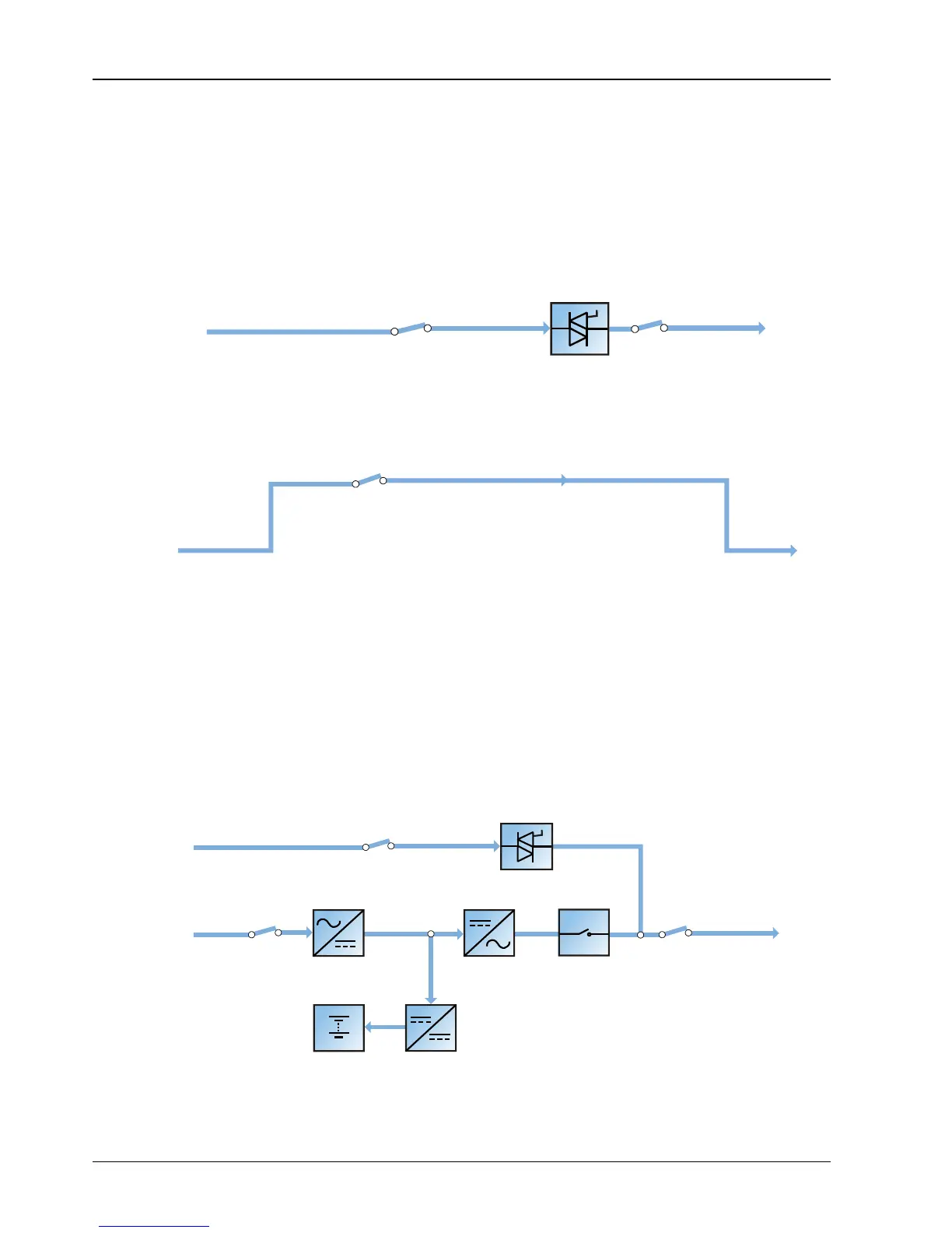
Bypass mode
As shown in Figure 1-5, in normal mode, in case of inverter failure, inverter overload or inverter manual shutdown, the
static switch will transfer the load from the inverter side to bypass side, with no interruption in power to the load. At this
time, if the inverter and bypass are not synchronized, the power of the load has transitory interruption, with time of less
than 20ms.
Figure 1-5 Schematic diagram of bypass mode
Maintenance mode
As shown in Figure 1-6, if the UPS maintenance or service is required, you may use the manual maintenance bypass
switch to transfer the load to maintenance bypass, with no interruption in power to the load. This maintenance bypass
switch is fitted in all UPS modules and rated for full load of one module.
Figure 1-6 Schematic diagram of maintenance mode
ECO mode
If ECO mode is selected, the double-conversion UPS operation is inhibited most of time for the purpose of saving
energy. In this mode, the bypass is the preferred source and only when the voltage and/or frequency of the bypass
supply are/is beyond the pre-defined threshold the critical AC load is transferred to the inverter: if the inverter is
synchronized with the bypass source, the transfer will be instantaneous and during the transfer the output waveform
will not exceed the limits set by IEC/EN 62040-3 for a UPS to be classified as VFI-SS-111.
If the inverter is not synchronized with the bypass, in order to avoid hazardous cross current, bypass/inverter
changeover is triggered only after a few milliseconds (maximum 20ms) from when bypass has been disconnected
from the load. Then, after bypass frequency and voltage have came back and remained within the predefined limits for
at least five minutes, the load is automatically and instantaneously transferred back to bypass source.
In this mode, the system can normally charge the battery.
Figure 1-7 Schematic diagram of ECO mode
If ECO mode is required, adjust the corresponding parameters through the operator control and display panel.