EasyManuals Logo

Lighthouse Worldwide Solutions ApexR3p User Manual

Lighthouse Worldwide Solutions ApexR3p
74 pages
To Next Page IconTo Next Page
To Previous Page IconTo Previous Page
Page #34 background imageLoading...
Page #34 background image
ApexRp Operators Manual
33 248083480-1 Rev 3
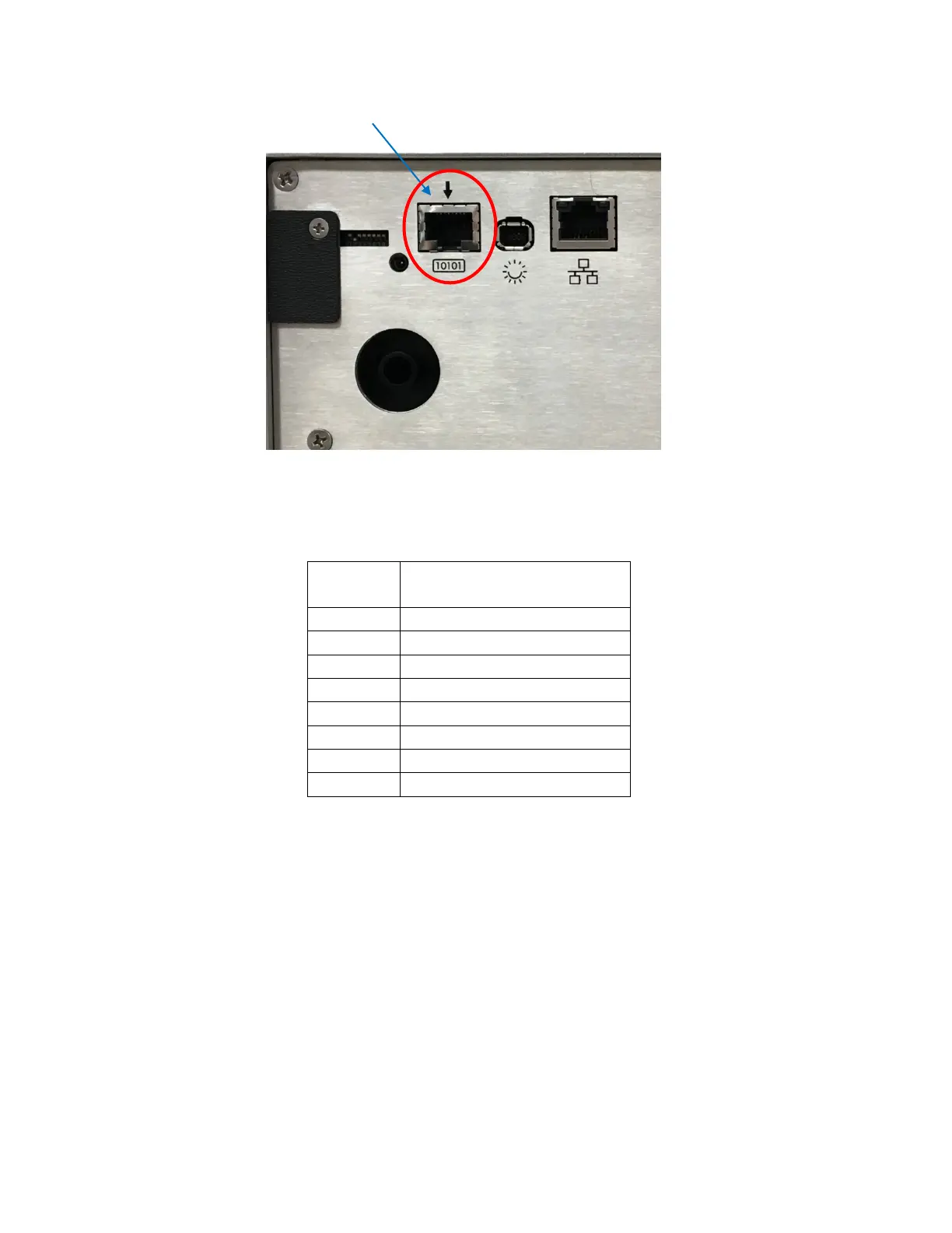
Figure 4-2 Serial COM Port
The connector pinouts are shown in Table 4-4.
RJ45 Pin
Signal Name
1
RS-232 TX (Output)
2
RS-232 RX (Input)
3
RESERVED for future use
4
RS-485B
5
RS-485A
6
RESERVED for future use
7
24 VDC
8
GROUND
Table 4-4 RJ45 Pinouts
To connect the instrument to an RS-485 network:
1. Make sure the SmartPort Cable is disconnected from the
instrument.
2. Install the ApexRp in a perpendicular position with its Inlet
barb upward. Connect one end of a CAT5e cable to the Serial COM
port on the instrument (shown in Figure 4-2).
3. Connect the other end of the cable to an available RS485 port on
an LWS 485 Gateway, an LWS System Control Cabinet RS485 port or
other similar equipment port.
Serial COM

Table of Contents

Questions and Answers:

Question and Answer IconNeed help?

Do you have a question about the Lighthouse Worldwide Solutions ApexR3p and is the answer not in the manual?

Lighthouse Worldwide Solutions ApexR3p Specifications

General IconGeneral
BrandLighthouse Worldwide Solutions
ModelApexR3p
CategoryRemote Control
LanguageEnglish