ApexRp Operators Manual
65 248083480-1 Rev 3
The Data Status flag is set if any of the channels have a threshold
exceeded state as true.
The threshold registers (45xxx series) run in parallel with the data
registers (30xxx series). For example, data register 30010’s
corresponding threshold register would be 45010. Data register
30016’s threshold register would be 45016.
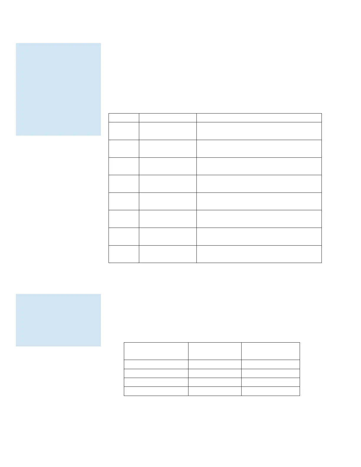
Table A-11 Alarm Threshold Registers
Setting the Alarm Threshold Value
The Alarm Threshold Value is set in the low register of the channels.
Each channel has independent threshold value registers. Setting a
value for channel 1 as 100 will not affect channel 2 setting of, say,
500.
Table A-12 Alarm Threshold Registers set to 1000
Threshold for Particle Channel 1 [high]
(smallest particle size starts here)
Threshold for Particle Channel 1 [low]
Threshold for Particle Channel 2 [high]
Threshold for Particle Channel 2 [low]
Threshold for Particle Channel 3 [high]
Threshold for Particle Channel 3 [low]
Threshold for Particle Channel 4 [high]
Threshold for Particle Channel 4 [low]
shows the registers for an
8 channel particle
counter. Counters with
fewer channels do not use
the extra registers. The
smallest particle channel
starts at the xxx09
position.
independent of each
other so the value set for
one channel does not
affect another.
 Loading...