1. Locate the Diagnostic Connector
The connector is generally located under the
dash at the fire wall on the driver side and is
usually protected by a plastic cover. To remove
the protective cover, you must push the cover
while turning counter clockwise, then pull to
remove it.
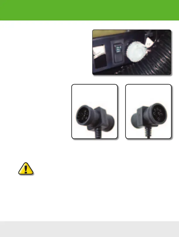
2. Determine Plug Type
The universal plug included with
your ScanGauge is compatible
with both the J1939 (9pin) and
J1708 (6-pin) diagnostic port.
Match the end of the plug to the
connector, but do not plug it in at
THIS time.
3. Locate a Place For The
ScanGauge.
You can use the sticky-back Velcro
®
supplied with the ScanGauge to attach it to the location you
have chosen.
DO NOT mount the ScanGauge over an air bag cover where it could be
propelled by a deploying airbag.
4. Route The Cable.
Route the cable from the ScanGauge to your vehicle’s diagnostic connector. Be sure to keep the
cord from interfering with the pedals or operating controls of the vehicle.
6-pin connects to vehicles
that use the J1708 protocol
9-pin connects to vehicles
that use the J1939 protocol
Installation
Typical J1939/J1708 protective cover
8 — www.ScanGauge.com