D9U001AM2-0101_06
27
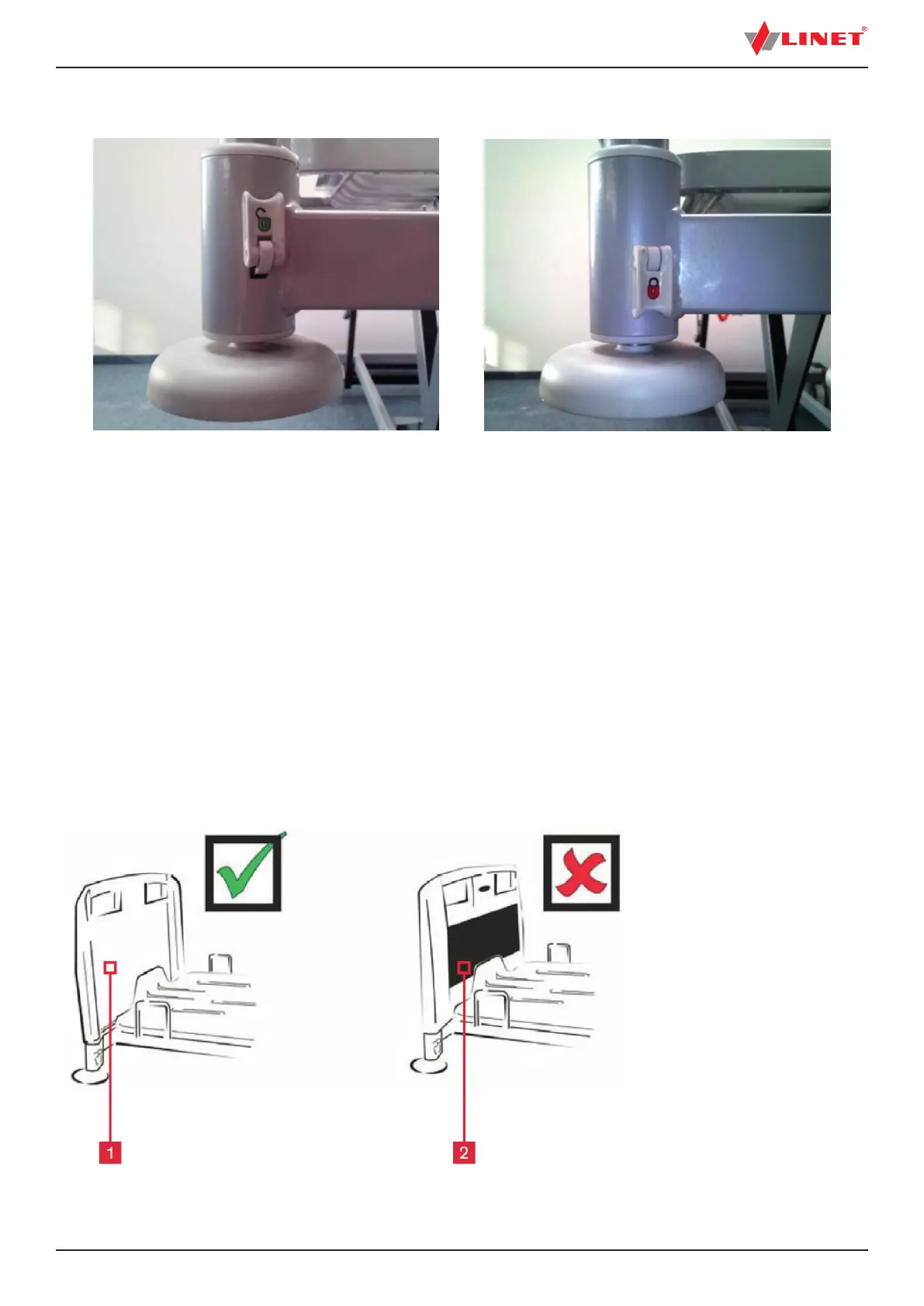
1. Right (coloured
panel outside)
2. Wrong (coloured
panel inside)
Fig. Installing the head board and foot board
NOTE: It is possible to install head board or foot board to the bushings with locked lock.
Fig. Unlocked position Fig. Locked position
1. Unlocked (the head board or foot board can be removed)
2. Locked (head board or foot board is locked)
9.2.2 Powder coated head board and foot board
Manipulation with head board and foot board
Insert the head board or foot board as follows:
► Unlock safety levers on corner posts (green lock - unlocked, red lock - locked).
► Slide head board or foot board into slots on corner posts with coloured panel on the outside.
► Lock safety levers on corner posts.
Remove the head board or foot board as follows:
► Unlock safety levers on corner posts.
► Pull head board or foot board upward.
9.2.3 Correct Orientation of Head Board and Foot Board
 Loading...