D9U001ES1-0101_08
27
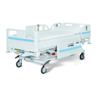
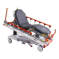
Fig. Manipulation with Siderail Release Mechanism at foot end Fig. Manipulation with Siderail Release Mechanism at head
end
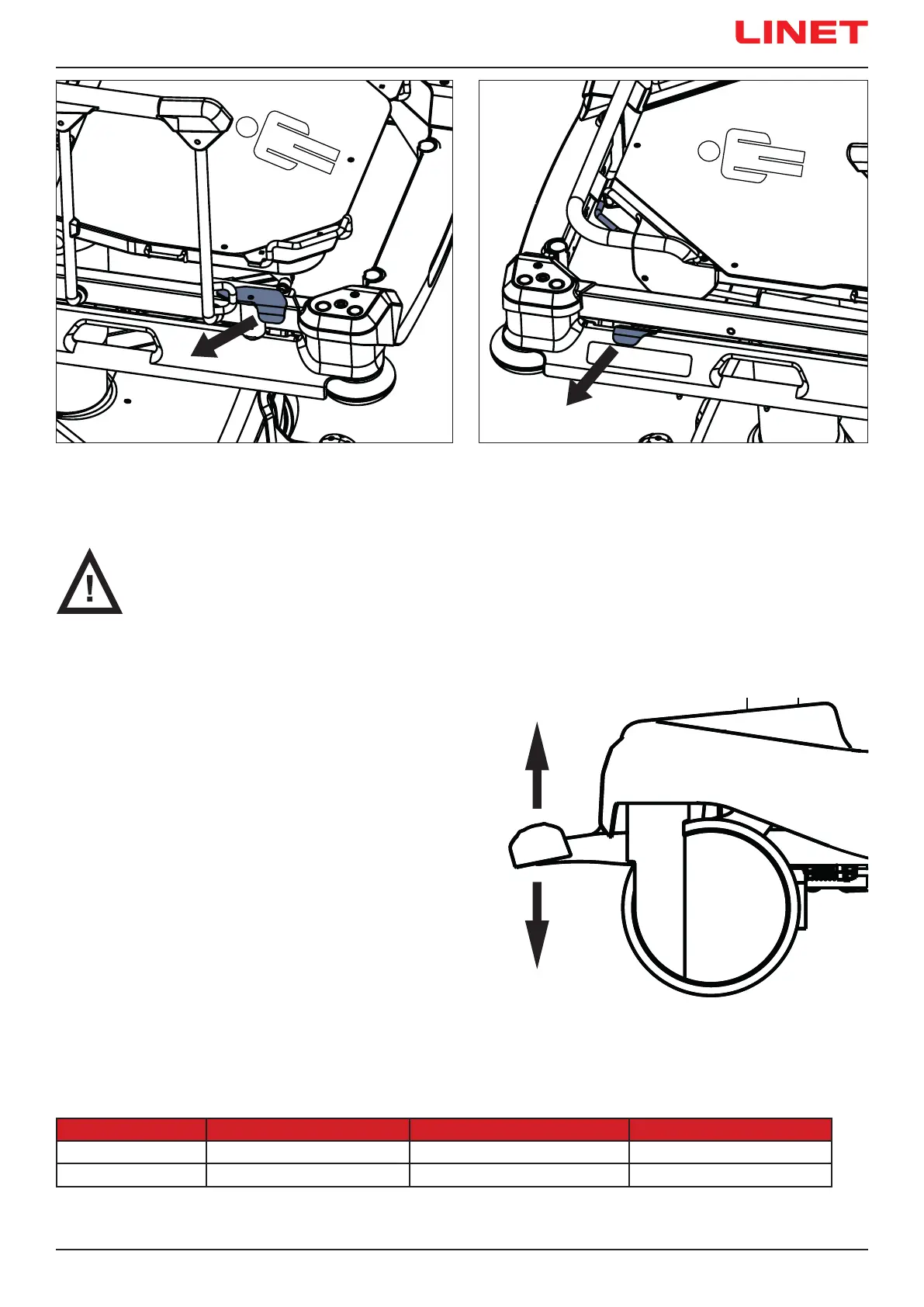
10.2 Castor Control
CAUTION!
Material damage due to incorrect transport and involuntary movement!
► Ensure that the castors are braked prior to assembly, disassembly and maintenance.
► Ensure that the castors are braked when the bed is occupied.
► Ensure that the castors are braked when the bed should not move.
The bed is equipped with central castor control and brake system.
A directional castor can be situated at head end or foot end
depending on bed conguration.
The castor control pedals are located at head end and foot end.
Optionally, castor control pedals are located on the bed sides also.
At head end and foot end there are green and red pedals.
Red colour refers to braking and green colour refers to steering.
Each pedal has 3 control positions.
Pedals are interconnected such that all pedal functions
belong to each pedal. In following table the pedal functions
are described.
Pedal Colour Upper Position (1) Middle Position (2)
GREEN BRAKED UNRESTRICTED MOVEMENT STEERING / FIFTH CASTOR
RED STEERING / FIFTH CASTOR UNRESTRICTED MOVEMENT BRAKED
Fig. Three Pedal Positions
1
2
3
 Loading...