D9U001ES1-0101_08
47
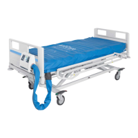
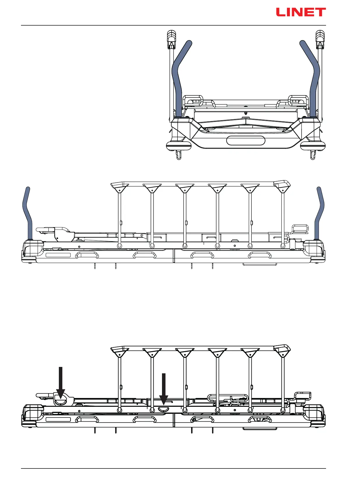
Fig. Fixed handles (front view)
Fig. Fixed handles on head end and on foot end (side view)
11.7.3 Fixed handles
Fixed handles are screwed to corners of the bed on head end
or on foot end. User is not allowed to change positions of the
Fixed handles. Removal and installation must be performed
by trained service technician according to the corresponding
service instruction provided by manufacturer.
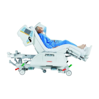
Fig. Angle Indicators
11.8 Angle Indicators (optional)
Angle Indicators are optionally situated on both sides of the Backrest or on both sides of the Backrest and on both sides of Mattress
Support Platform frame in seat section. Backrest angle indicators are intended for an approximate Backrest angle measurement.
Angle indicators in the seat section are intended for an approximate measurement of Trendelenburg tilt and Anti-Trendelenburg tilt.
 Loading...