Chapter 5
Advanced Configuration
11
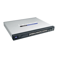
24-Port 10/100 + 2-Port 10/100/1000 Gigabit Advanced Smart Switch with 2 Combo SFPs
Web Admin Timeout
Enable Web Admin Timeout (Web/Console) When this
option is enabled, the admin will be logged out of the
web-based utility after the idle time specified in the Web
Admin Timeout field has been reached.
Web Admin Timeout Defines the amount of idle
time (in seconds) required before the admin account is
automatically logged out of the web-based utility.
NOTE: Entering 0 in the Web Admin Timeout
field disables the Web Admin Timeout.
Identification
System Name Specifies the name of the Switch. Enter
the name into the text field provided. By default, a system
name is not defined.
System Location This field is used for entering a
description of where the Switch is located, such as 3rd
floor.
System Contact Enter the name of the administrator
responsible for the system.
System Object ID The system object identifier is
displayed here.
MAC Address Physical address of a device mapped to
this interface.
IP Configuration
IP Address Mode Specifies whether IP functionality is
enabled via manual configuration (Static) or dynamically
using Dynamic Host Configuration Protocol (DHCP).
NOTE: If DHCP is enabled, IP will not function
until a reply has been received from the server.
Requests will be broadcast periodically by the
Switch for an IP address. If the mode is set to
DHCP and a server is not available, you can
reconfigure the settings by connecting the
console interface directly to a computer.
Select the IP Address Mode using the drop-down
menu. Selecting Static will allow you to enter a static
IP address, subnet mask and default gateway using the
text field provided. Selecting DHCP disables these text
fields and the Switch attempts to obtain an IP address
automatically from a DHCP server. The default setting is
Static.
Management VLAN ID of the configured VLAN (1-4094,
no leading zeroes). By default, all ports on the Switch are
members of VLAN 1. However, the management station
can be attached to a port belonging to any VLAN, as long
as that VLAN has been assigned an IP address.
IP Address Address of the VLAN interface that is allowed
management access. Valid IP addresses consist of four
numbers, 0 to 255, separated by periods. (Default:
192.168.1.254)
Subnet Mask This mask identifies the host address
bits used for routing to specific subnets. (Default:
255.255.255.0)
Default Gateway IP address of the gateway router
between this device and management stations that exist
on other network segments. (Default: 0.0.0.0)
Setup > Time
Simple Network Time Protocol (SNTP) allows the Switch
to set its internal clock based on periodic updates from a
time server (SNTP or NTP). Maintaining accurate time on
the Switch enables the system log to record meaningful
dates and times for event entries. If the clock is not set, the
Switch will only record the time from the factory default
set at the last boot up. When the SNTP client is enabled,
the Switch periodically sends a request for a time update
to a configured time server.
Setup > Time
Current Time
Current Time The current time of the Switch is displayed
here.
Local Time
Configure Local Time This option allows you to set the
time and date manually for the Switch.
Mon The month is entered here.
Day The day is entered here.
Year The year is entered here.
Hour The hour is entered here.
Min The minute is entered here.
•
•
•
•
•
 Loading...