Rev:11.08.19 Page 133 CCD-0001573-08
Hitching to Tow Vehicle
1. Chock the tires of the trailer.
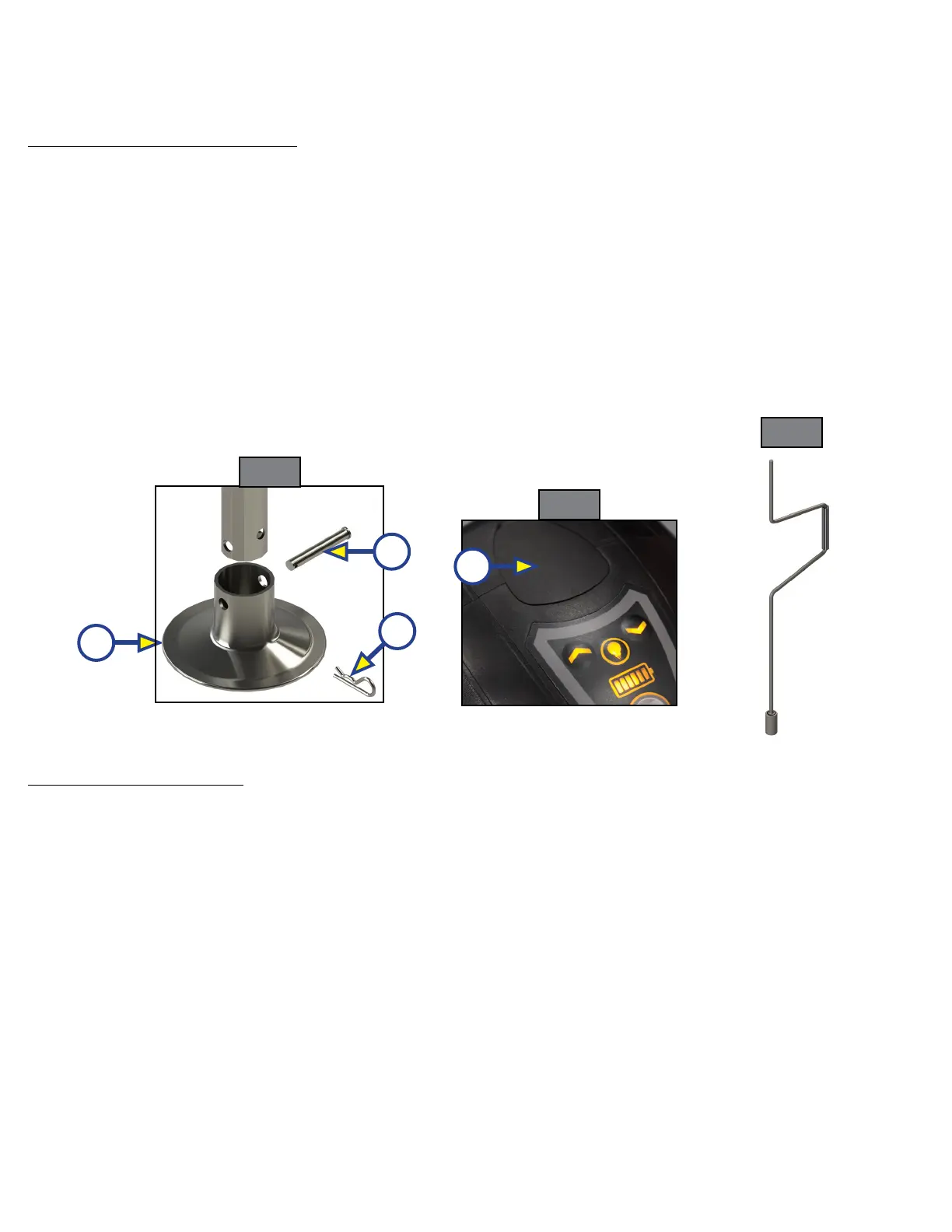
2. Be sure the footpad (Fig. 2A) of the Smart Jack is pinned
securely in place with the Clevis Pin (Fig. 2B) and Hairpin Cotter Pin (Fig. 2C).
3. Remove the manual drive shaft plug (Fig. 3A) on top of the Smart Jack’s gearbox.
4. Insert the manual crank handle (Fig. 4) onto the manual drive shaft.
5. Turn the crank handle counterclockwise until the coupler properly mounts the hitch ball and the leg of
the Smart Jack is fully retracted.
NOTE: The crank handle may need to be initially turned clockwise to extend the jack to clear the hitch ball
prior to retracting the jack.
6. Remove the crank handle (Fig. 4) from the drive shaft.
7. Reinsert the manual drive shaft plug (Fig. 3A).
NOTE: Make sure the leg of the Smart Jack is fully retracted before moving the tow vehicle.
Manual Operation
If 12V DC power is unavailable to operate the Smart Jack, use the following directions to manually operate
the Smart Jack.
Unhitching From Tow Vehicle
1. Chock the tires of the trailer.
2. Be sure the footpad (Fig. 2A) of the Smart Jack is pinned securely in place with the Clevis Pin (Fig. 2B)
and Hairpin Cotter Pin (Fig. 2C).
3. Make sure the ground surface under the Smart Jack footpad is firm and level.
4. Remove the manual drive shaft plug (Fig. 3A) on top of the Smart Jack’s gearbox.
5. Insert the manual crank handle (Fig. 4) onto the manual drive shaft.
6. Turn the crank handle clockwise to extend the jack until the trailer is supported and the coupler clears
the tow vehicle's hitch ball.
7. Move the tow vehicle a safe distance away from the trailer.
8. Turn the crank handle either direction as needed until front of the trailer is level.
9. Remove the crank handle (Fig. 4) from the manual drive shaft.
10. Reinsert the manual drive shaft plug (Fig. 3A).
A
B
C
A
Fig. 2
Fig. 3
Fig. 4