Rev:11.08.19 Page 149 CCD-0001573-08
NOTE: Steps 2-5 are identical for both 4-Point and 6-Point Leveling Systems.
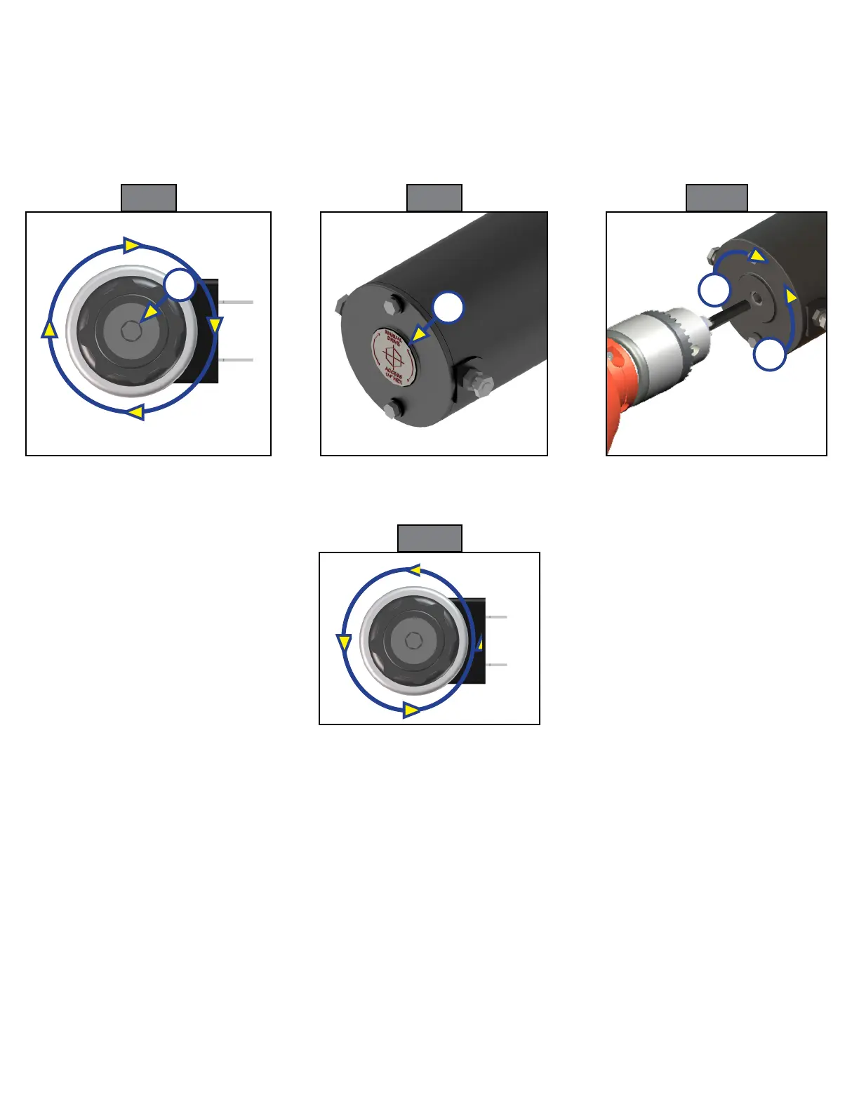
2. Using a 5/32” hex wrench, open the valve by turning the manual override set screw clockwise (Fig. 8).
3. Remove protective label (Fig. 9A) from power unit motor to reveal the manual override coupler.
4. Using an electric drill with a 1/4” hex bit, insert the hex bit into the manual override coupler (Fig. 10) to
manually operate the system.
A. Run the drill forward (clockwise) (Fig. 10A) to retract the landing gear or leveling jacks.
B. Run the drill in reverse (counterclockwise) (Fig. 10B) to extend the landing gear or leveling jacks.
5. Make sure to turn the manual override set screw on the valve back to the counterclockwise position
(Fig. 11) after extending or retracting the landing gear or leveling jacks.
A
A
A
B
Fig. 8 Fig. 9 Fig.10
Fig. 11