21
VALVES
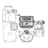
Single Stage Valves
Earth/Green (16)
Out7/Black (15)
+12V/Black (14)
84040 Board
SOLENOIDS J13
Jumper from
Terminal 15
to Terminal 18
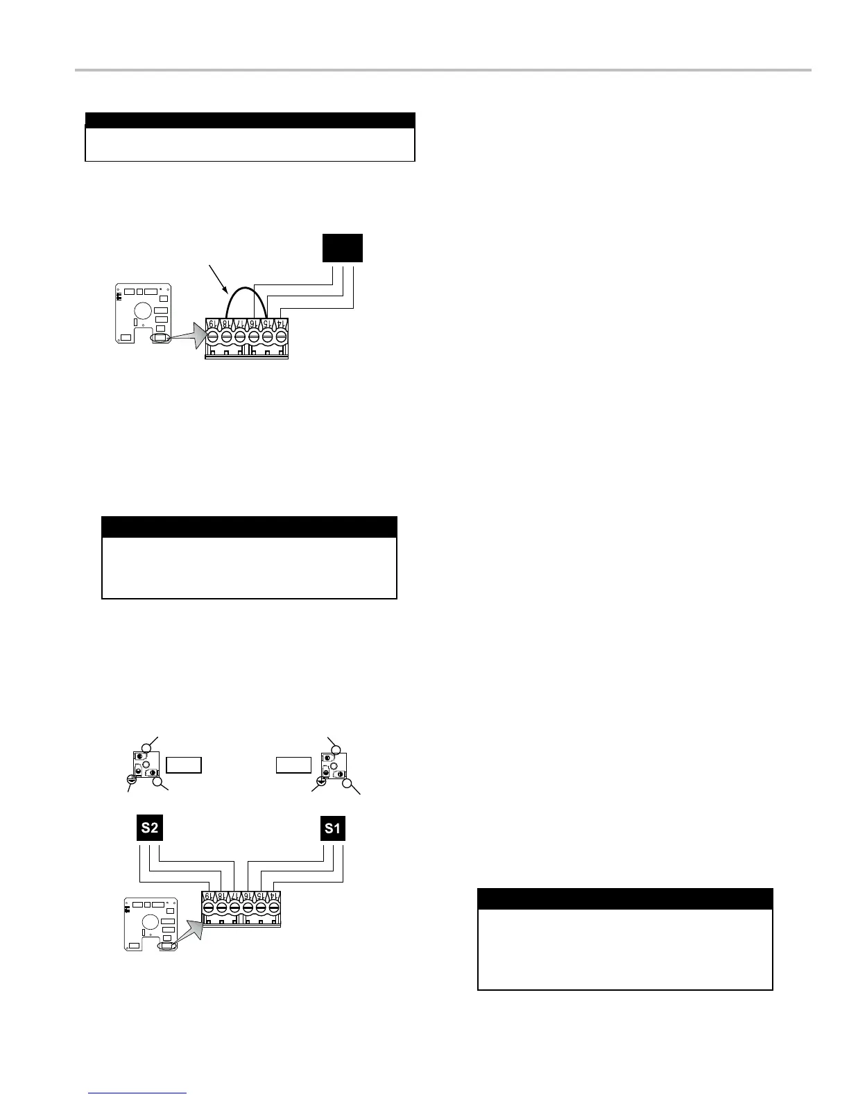
S1&2
Connector
Block S2
Connector
Block S1
84040 Board
SOLENOIDS J13
Earth/Green (16)
Earth/Green (16)
Earth/Green (19)
Earth/Green (19)
Out7/Black (15)
Out7/Black (15)
Out6/Black (18)
Out6/Black (18)
+12V/Black (14)
+12V/Black (14)
+12V/Black (17)
+12V/Black (17)
2
1
2
1
Valve Installation
installation and operation manual for mechanical
installation. Instructions for wiring Liquid Controls valves
to the LCR-II are on the following two pages.
Materials needed for wiring valves:
Not supplied
with the valve
Not necessary for
3-Way solenoid valves. Only 2 needed for E7 solenoids.
conduit connectors or cable glands
To wire valves to the LCR-II:
1. Attach cable glands and/or conduit connectors to the
solenoid valve(s) and the LCR-II port(s).
2. Thread the wires through piece of weatherproof conduit
that is cut-to-length from the solenoid to a LCR-II port.
3. Run the weatherproof conduit between the solenoid-
operated valve(s) and the LCR-II housing, pull the wires
through the ports, and tighten the connectors.
4. Connect the S1 solenoid-operated valve wires to
II CPU board.
5. Connect the S2 solenoid-operated valve wires to
II CPU board.
To wire a single stage valves for presetting:
Disconnect the power before working on the CPU board.
Disconnect Power
Solenoid operated valve 81527 (3-way LPG solenoid)
has 3 cables potted into the housing. All other
solenoid operated valves on Liquid Controls valves
use cable assembly 81859, which has 2 cables.
Solenoid Operated Valve Cables
The Earth grounds for Terminals 16 & 19 are optional.
The solenoid operated valves are grounded through
the component they are mounted on.
Earth Grounds for Solenoid Valves

 Loading...