Lite-On Technology Corp.
Industrial Automation
14
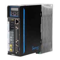
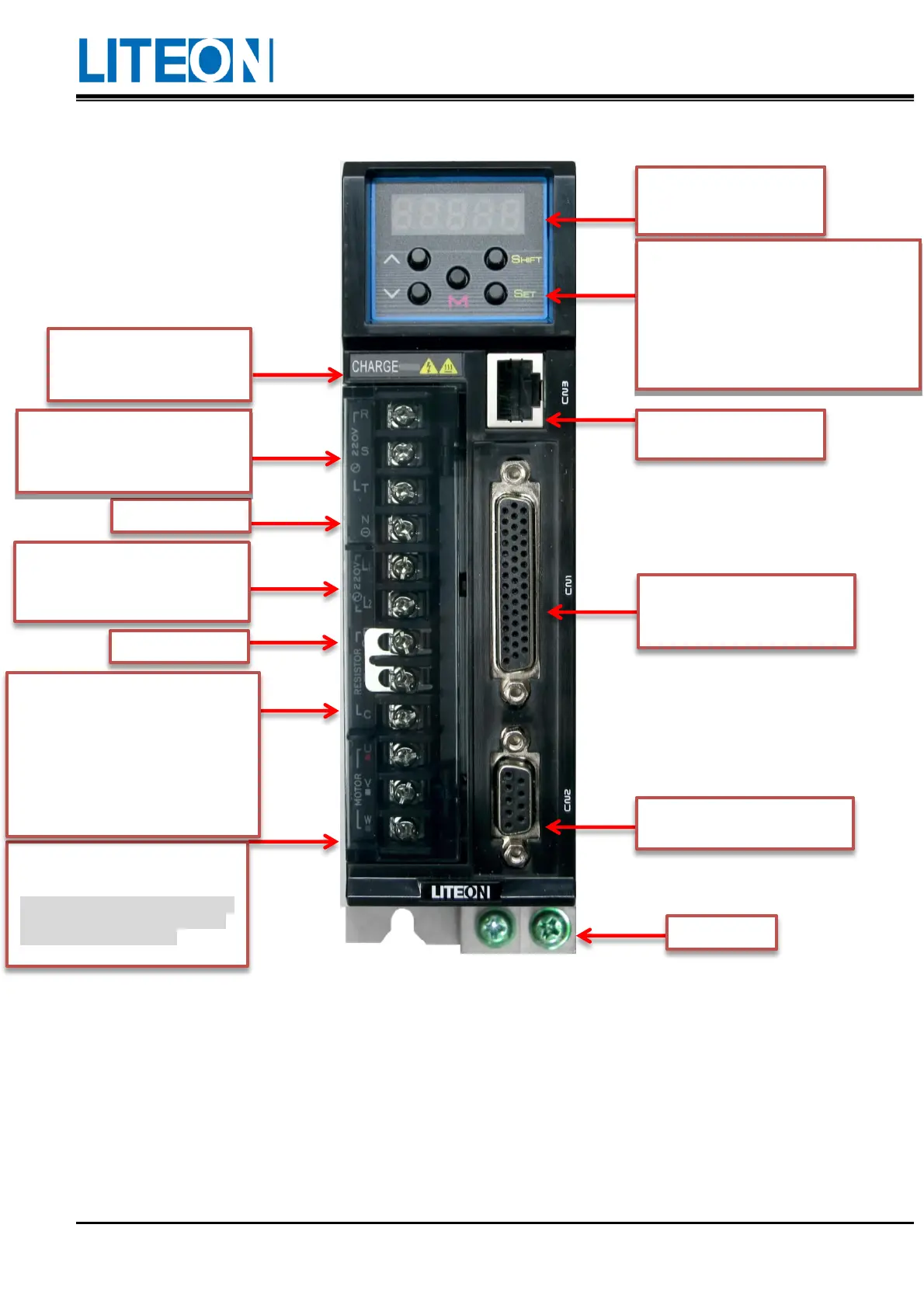
1.3. Name of each part in the servo drive
Seven-segment display: It
has five digits and shows the
Operating button: It can be used to switch the
parameter/function and execute the
monitoring setting.
MODE: It is used to return to the previous
level or switch the status.
UP/
DOWN: It is used to add or minus one.
SET: It is used to confirm the setting.
SHIFT: It is used to move the digit to the left.
CN3: It is used to connect to
the PC software.
CN1: It is used to connect to the
upper controller, such as the PLC
or industrial computer.
CN2: It is used to connect to the
motor encoder.
Motor power output: It is used to
connect to the motor UVW cable.
Do not connect to the power supply of
the main circuit. Wrong connections
may result in drive damage!
1) When the external regenerative
resistor is used, the P and C ends
connect to the resistor and the P and D
ends are open-circuit.
2) When the internal regenerative
resistor is used, the P and C ends are
open-circuit and the P and D ends must
Power supply of the control circuit:
The L1 and L2 supply for the single-
phase 100~230Vac and 50/60 Hz
Power supply of the main circuit: R,
S and T are connect to the
commercial power supply (AC
Power indicator: There is
voltage remained in the main
circuit when the light is on.
 Loading...