Lite-On Technology Corp.
Industrial Automation
24
Chapter 3 Wiring
The chapter explains the connecting method of the servo drive and the meaning of all signals. It also
lists the illustration of the standard wiring in various modes.
3.1. Connection for the peripheral device and main power circuit
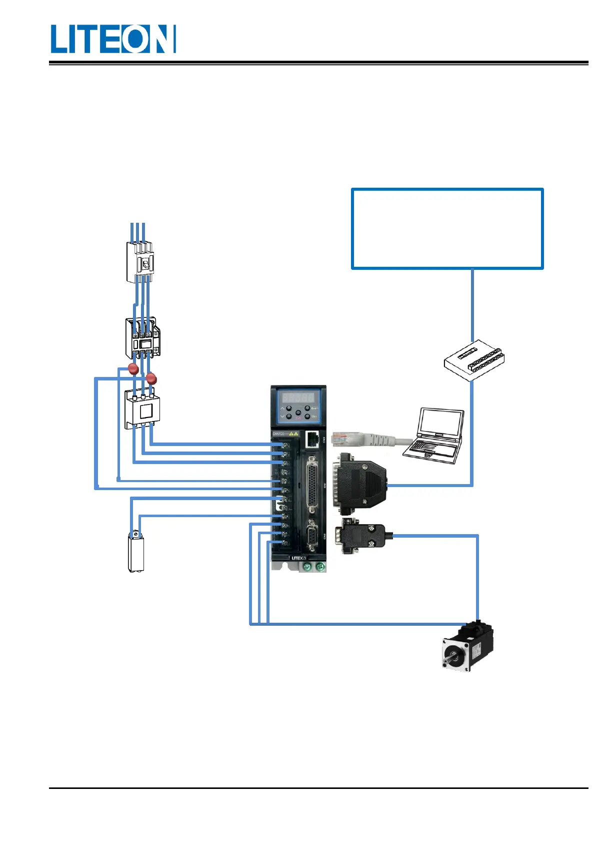
3.1.1. Wiring diagram of the peripheral device
Upper controller
PLC
PC-Based Control
HMI
100W~1kW Single-phase/three-phase 200V~230V
1.5kW~2kW Three-phase 200V~230V
It is set for prevention of the drive
damage due to excessive amount of
instantaneous current caused by switch
turning or short circuit.
When an alarm occurs, the magnetic contactor can
be used with the servo drive to output the alarm
(ALRM) signal to control the magnetic contactor
(MC) to disconnect the power supplied to the servo
drive.
Use a proper EMI filter
and a correct installation
method to diminish the
interference.
To prevent the
abnormality caused by
the braking of the servo
motor, use the external
regenerative resistor to
connect to the P+ and D
ends of the servo drive to
open the circuit. If using
the internal regenerative
resistor, short the circuit
for the P+ and D ends
and open the circuit for
the P+ and C ends.
The terminal block
transfers the signal
of CN1 50PIN to the
controller.
It can be connected to
the PLC controller and
HMI or other NC
controllers.
CN3 communication connector
1. The connector is
controlled via Modbus
and supports RS232/485.
2.
ISA-Pro is used for
tuning, parameter setting
and control.
Connect the encoder signal
of the servo motor to the
servo drive.
It is connected to the
upper controller via I/O
connection.
 Loading...