Lite-On Technology Corp.
Industrial Automation
67
4.4.3. Enforced operation of the digital output
Enter the output diagnosis mode according to the setting method below.
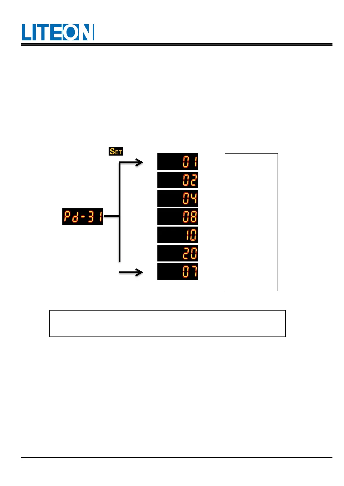
Set "PD-44=006" first and turn on the enforced DO mode. Use the PD-31 to set the enforced DO output via
the binary system.
E.g.: DO2 is turned on forcefully when the value is set to 2.
DO1 and DO3 are turned on forcefully when the value is set to 5.
No memory is saved for this mode after power off. The regular DO mode can be resumed after power on or
setting "PD-44=106".
DO1, DO2 and
DO3 turned on
forcefully
4.4.4. Operation for the diagnosis of digital input
Enter the input diagnosis mode according to the setting method below.
When the triggering is executed via the external input signals DI1 ~ DI9 , the panel display shows the
corresponding signal. The signal is displayed in the hexadecimal character format.
bit0 corresponds to DI1; bit1 to DI2...etc. The value 1 indicates triggering.
E.g.: If "1A1" shows on the display, the binary value is 110100001b, indicating the triggering for DI1, DI6,
DI8 and DI9.
The PD-31 is in the hexadecimal format. The numerical value 0 at the fifth digit
does not appear.
 Loading...