EasyManuals Logo

LiteOn ISA-7-040-S1 User Manual

LiteOn ISA-7-040-S1
237 pages
To Next Page IconTo Next Page
To Previous Page IconTo Previous Page
Page #69 background imageLoading...
Page #69 background image
Lite-On Technology Corp.
Industrial Automation
69
4.4.5. Operation for the diagnosis of digital output
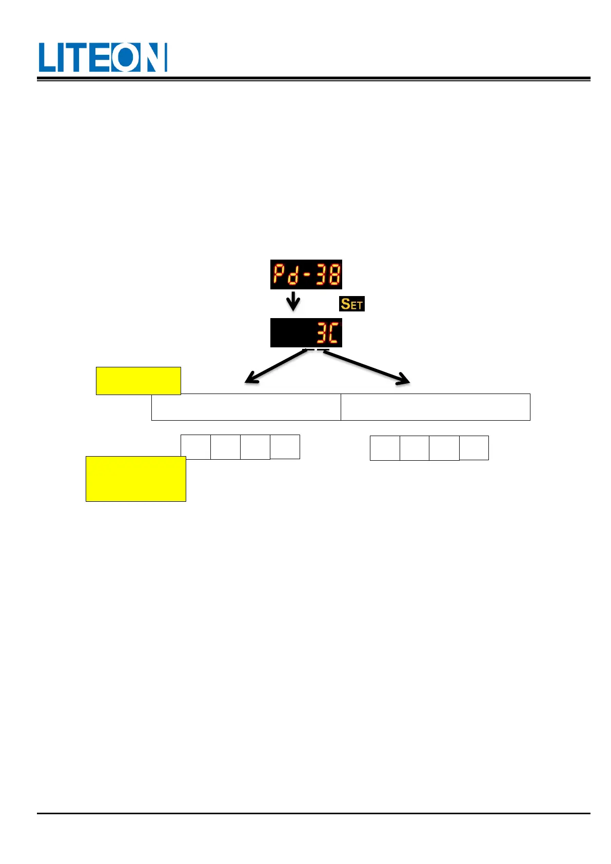
Enter the output diagnosis mode according to the setting method below.
As for the electrical conductivity of the output signals DO1 ~ DO6, the signal corresponding to these output
signals shows on the panel display. The signal is displayed in the hexadecimal format. bit0 corresponds to
DO1; bit1 to DO2...etc. The value 1 indicates triggering.
E.g.: If "3C" shows on the display, the binary value is 00111100b, indicating the triggering for DO3, DO4,
DO5 and DO6.
0 0 1 1
1 1 0 0
DI
1
DI
2
DI
3
DI
4
DI
5
DI
6
DI
7
DI
8
Binary code
Corresponding
DI state
(Hexadecimal display)

Table of Contents

Questions and Answers:

Question and Answer IconNeed help?

Do you have a question about the LiteOn ISA-7-040-S1 and is the answer not in the manual?

LiteOn ISA-7-040-S1 Specifications

General IconGeneral
BrandLiteOn
ModelISA-7-040-S1
CategoryServo Drives
LanguageEnglish

Related product manuals