CHAPTER 3: SETTING INTO OPERATION 3-7
QUICK LOAD SERVO III MI
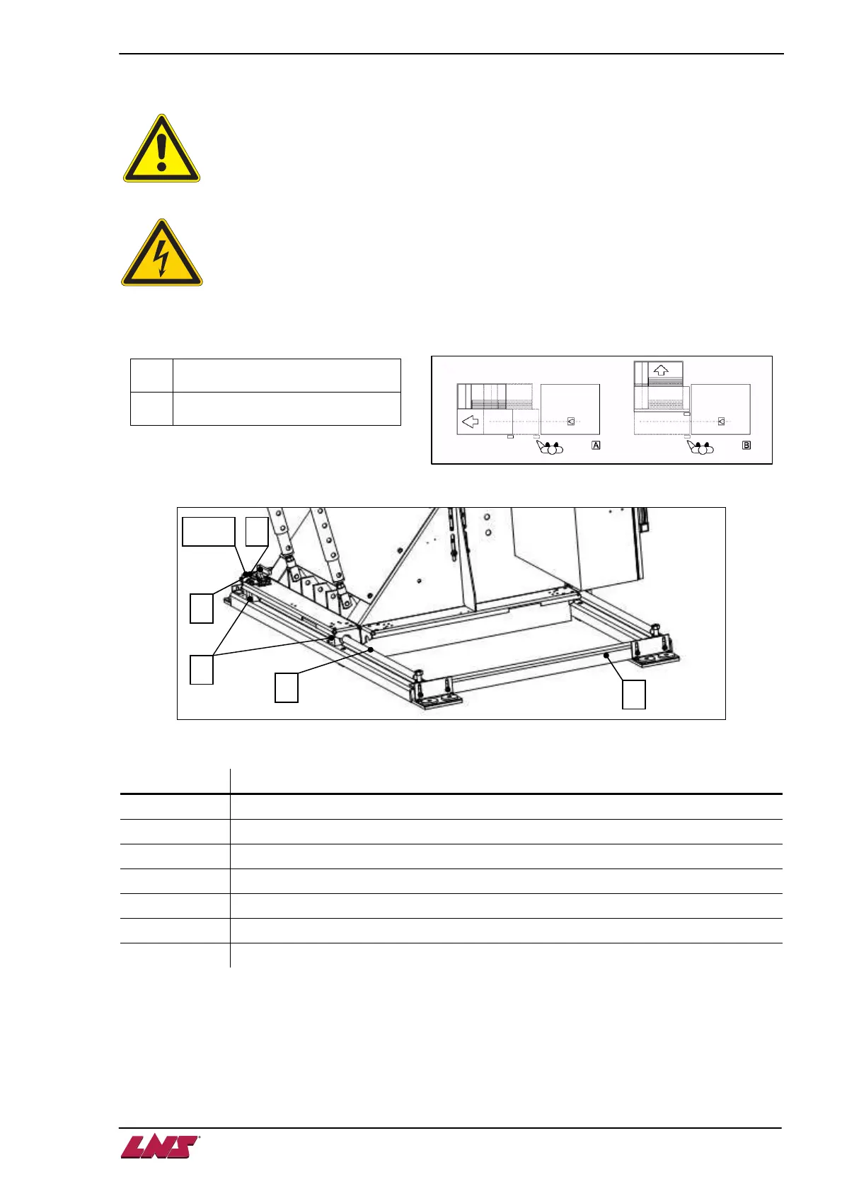
2.3. Mounting retraction device
Please read the safety precautions described at the beginning of this manual before
handling the following devices.
Before handling the retraction mechanism, check to see that the interface cables between
the spindle and the bar feed system are long enough
The retraction mechanism may be assembled as necessary, to ensure longitudinal or lateral movement.
A
Longitudinal retraction for
Left/Rear Load
B
Lateral retraction for Left/Rear
Load
Designation Description
A Guiding rails
B Sliding bearings
C Latches
D Latch handle
E Bracket (for lateral or longitudinal retraction)
F Auto lock device (not shown here)
SQ12 Retraction system in position switch
On delivery, the elements of the retraction mechanism are not assembled on the bar feed system, as they
can be installed either laterally or in line with the lathe.
 Loading...