CHAPTER 6: GENERAL DESCRIPTION 6-7
QUICK LOAD SERVO III MI
2. LOADING TABLE
Please read the safety precautions described at the beginning of this manual before
handling the following devices.
2.1. Description
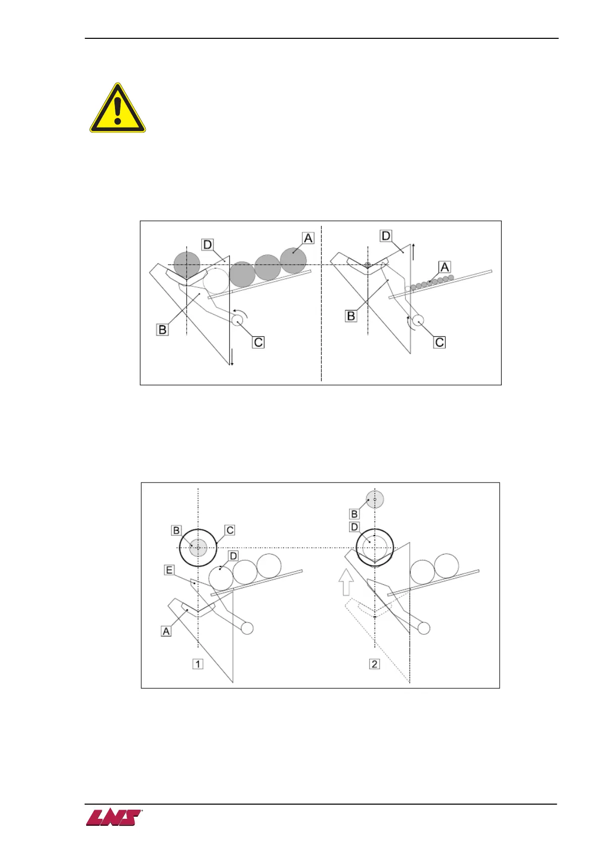
When positioned on the magazine, the bars rest against the loading fingers (B). The fingers are located
on an axle (C) connected to the loading table (D). The setting of the fingers is done automatically by the
M2 electrical motor at the same time as the setting of the loading table (centerline height).
The loading table of the Quick Load Servo III MI bar feed system has two functions:
1. Selection of material:
When slide (A) is in a low position, feeding pusher (B) faces spindle (C). The pneumatic
cylinders are activated, the channel rises and selects a bar (D) leaning against the stops (E) of
the loading table.
2. Guiding the material:
When in a high position, the loading channel faces the spindle. The bar can then be introduced
into the spindle.
In order for the bar always to be perfectly aligned with the center of the spindle, regardless of its diameter,
the height of the loading table is automatically set by a motor (M2) when the diameter of the bar is
entered into the parameters (See Chapter 7 / point 4.2.1).