6-6 CHAPTER 6: GENERAL DESCRIPTION
QUICK LOAD SERVO III MI
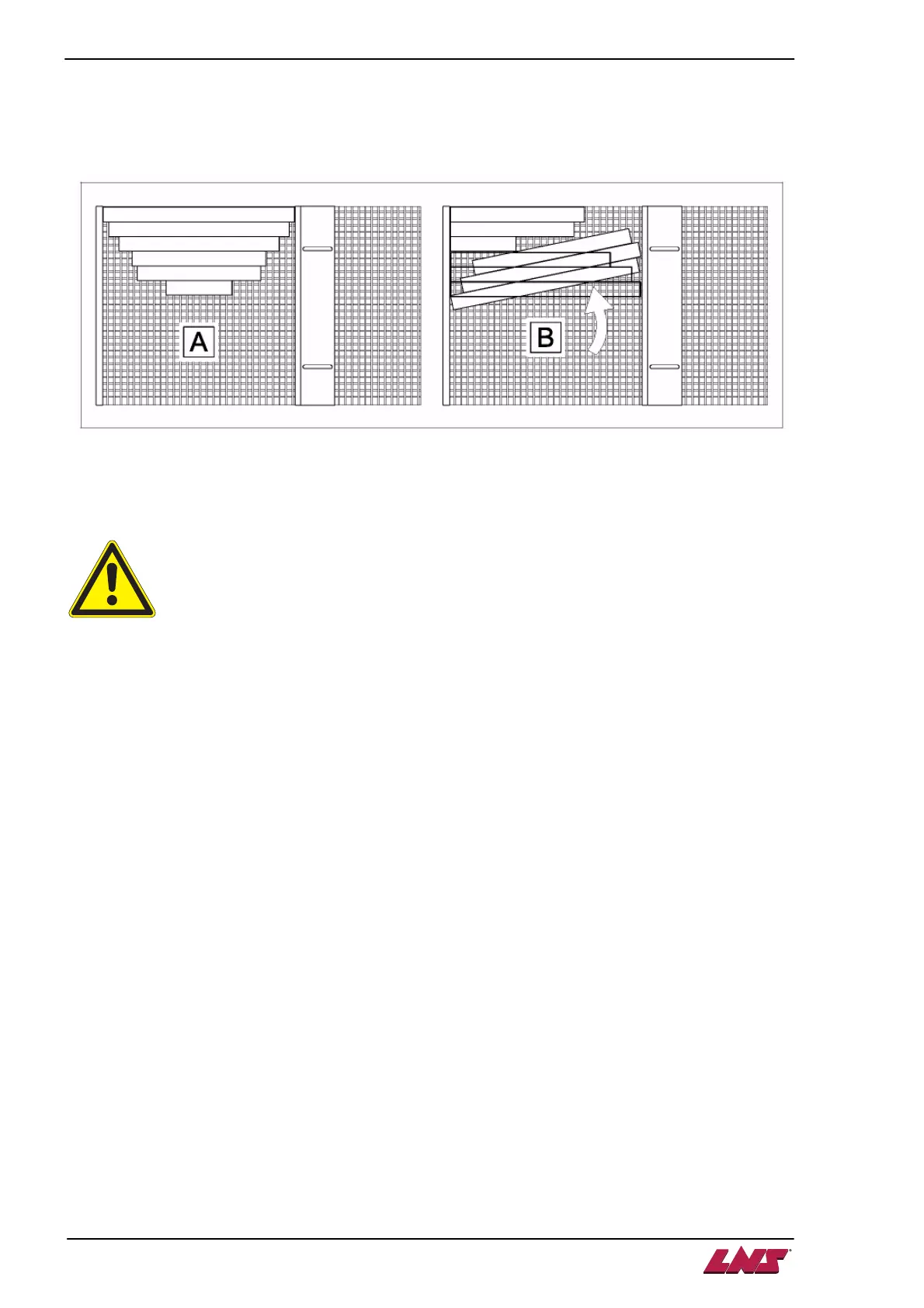
1.4.2. Loading variable bars
Although the Quick Load Servo bar feed system can load bars of various lengths it is advisable to place
them on the loading table in order of decreasing length, and to center them (A) between the limiters so
that they do not go side-ways (B).
1.4.3. Loading constant bars
Quick Load Servo III MI may also be used as a loading magazine for piston rods, axles, or forged parts.
A corresponding interface, however, is required if one wishes to attain minimum loading
times. These possibilities should be studied beforehand and discussed with the
manufacturer of the lathe or the Distribution Company.
When the parts are of the same length, it is possible to move the rear limiter to decrease the loading time.
• Lift the protection grid.
• Place a bar on the loading table, leaning against the front limiter.
• Move the rear limiter to 1 mm behind the bar. Check that the limiter is parallel by rolling the bar on
the table.
• Tighten the lock screws.
• Lever la grille de protection.
• A parameter must be changed, see chapter 7 / point 4.2.1
To facilitate the moving of the bars on the magazine table, the latter is equipped with a grate on which the
bars are placed. If, however, certain bars (i.e. profiled bars) cannot slide, the slope can be increased via
an axle located under the table. If, on the other hand, bars with small diameters overlap, then the slope
can or must be reduced.
1.4.4. Loading of profiled bars
According to the profile of the bars to be loaded, some settings and some optional accessories are
necessary. Please contact your LNS agent.