CHAPTER 6: GENERAL DESCRIPTION 6-9
QUICK LOAD SERVO III MI
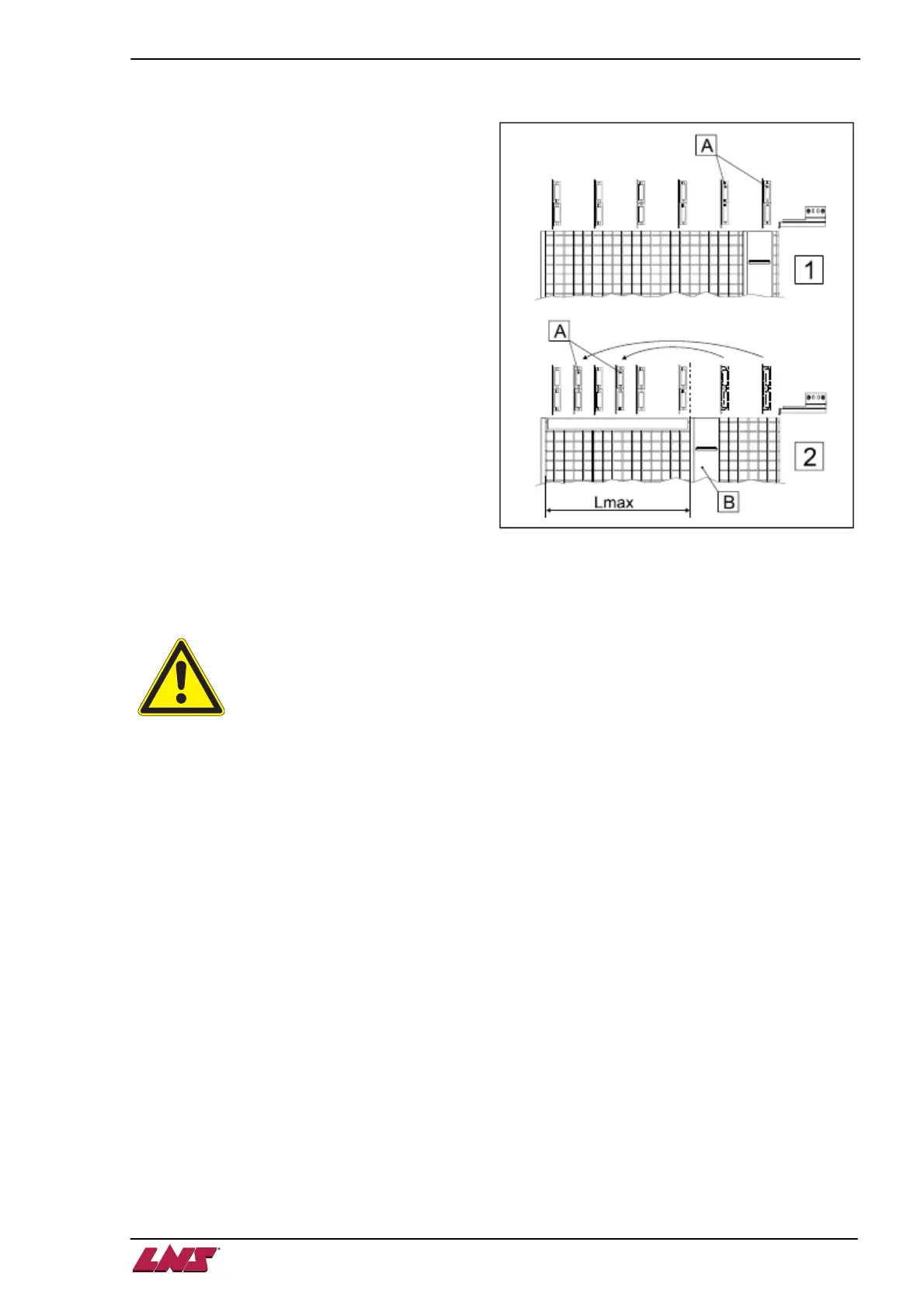
2.3. Positioning the roller supports
Quick Load Servo III MI is delivered initially with 6
roller supports, laid-out to cover the entire length
of the bar magazine.
When limiter (B) is positioned during the
installation (See point 1.4.1 / Lmax.), move the
supports (A) installed behind the limiter and install
them in the front, to assure better support of the
bar.
3. PUSHER CARRIER
Please read the safety precautions described at the beginning of this manual before
handling the following devices.
3.1. Description
By means of a timing belt, the SERVO motor starts drives the carrier. While the loading pusher is
advancing towards the spindle, the feeding pusher remains stationary. When the carrier returns to its
home position, the feeding pusher is locked, which, at that point, is attached to the carrier.
The locking/unlocking mechanism of the feeding pusher is pneumatically connected to the valves of the
loading channel :
1. Loading channel in loading position (upper position)
The loading pusher faces the spindle, the feeding pusher is not locked.
2. Loading channel in working position (lower position)
The feeding pusher faces the spindle, the feeding pusher is locked onto the carrier.
The length of the feeding pushers is unvarying and does not depend on the length of the spindle. For
safety reasons, the feeding pushers are equipped with a mechanical stop.
To load tubes, profiled bars or short bars, optional accessories may be installed. Please contact your
local LNS representative.