6-8 CHAPTER 6: GENERAL DESCRIPTION
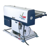
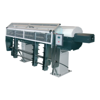
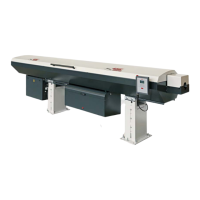
QUICK LOAD SERVO III MI
2.2. Loading table calibration
In order to ensure optimal loading, it is essential that the bar be perfectly aligned with the spindle,
regardless of its diameter. Whenever the diameter or the profile is changed, the position of the table is
automatically adjusted according to the diameter and the profile entered in the Quick Load Servo III MI by
the operator.
If, for any reason whatsoever, the position of the table should be incorrect (either too high or too low), it
can be corrected.
The pneumatic cylinders, controlling the vertical movement of the table, release the
pressure to allow motor M2 to proceed with the setting. After the setting is complete, they
are reactivated.
• Bars are on the magazine
• The loading table is in lower position
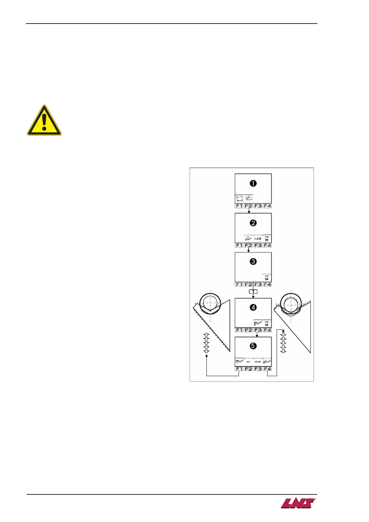
1. Select manual mode by pressing the [F2] key.
2. Bring the loading table in upper position [F2].
3. The bar now faces the spindle of the lathe.
4. The remote command offers icon [F4] Forward.
To obtain the icon [F1] Adjust the height of the
loading table, press and hold the [F3] key until
the icon shows up.
5. Press the [F1] key.
6. Three icons are displayed :
[F1] lower the table
[F3] ENTER (save)
[F4] raise the table
Each time the [F1] or [F4] key is pressed, the
vertical position of the table is modified by 0.25
mm. For substantial adjustments, keep pressing
the key to keep the table moving in a continuous
motion.
7. When the desired position is reached, press the
[F3] ENTER key to validate the choice and
recalibrate the device at this new position.
8. Since the calibration must be changed, the
command automatically accesses "Parameters
related to set-up, diameter, length, etc.
The command asks the operator to confirm the setting of the diameter.
9. Using the keypad, enter the diameter of the bar used to center the table. Press the [F3] ENTER
key twice to validate.