CHAPTER 6: GENERAL DESCRIPTION 6-15
QUICK LOAD SERVO III MI
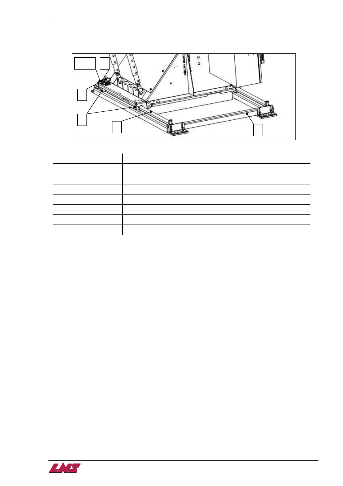
7.2. Layout of the elements
Designation Description
A Guiding rails
B Sliding bearings
C Latches
D Latch handle
E Bracket (for lateral or longitudinal retraction)
F Auto lock device (not shown here)
SQ12 Retraction system in position switch
7.3. Use of the retraction
Mounted onto four extremely rigid bearings (B), the bar feed system slides on two cylindrical rails (A) that
keep it aligned when it is in operational position. In this position, the bar feed system is fastened by two
solid hooks (C).
A safety switch (SQ12) impedes any handling as long as the bar feed system is not in operational
position.
• To move the bar feed system, unlock the hooks by lifting the latching handles (D). An autolock
device (F) will prevent the bar feed system to move back.
• To bring the bar feed in operational position, lift the auto lock device.