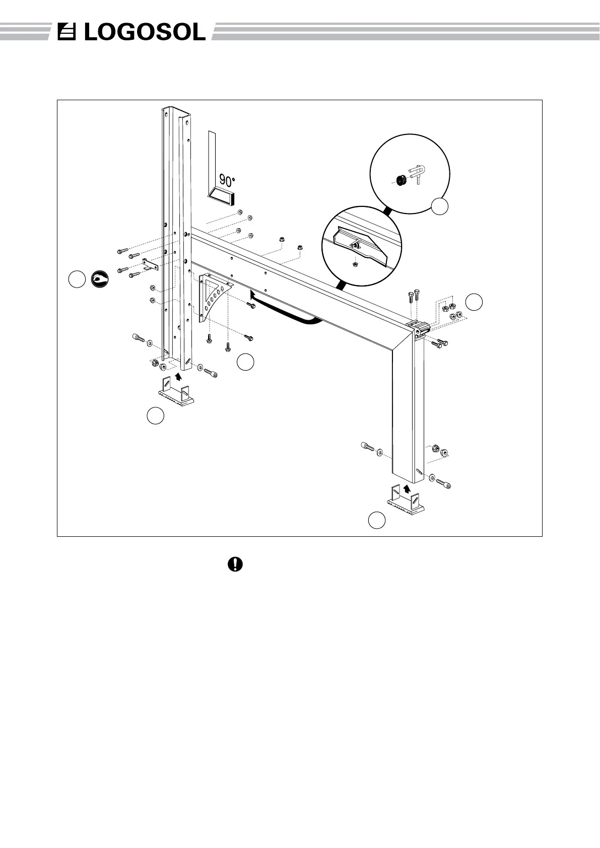
Assembly: Frame
The right and left leg units of
the frame are assembled in the
same way. The bolts listed
below are for one leg unit.
(1) Fit the horizontal beam to the
short leg using the corner tting.
Be careful not to damage the
bevelled faces before assembly.
(4 x M6x20 bolts, 4 x M6 collar
nuts)
(2) Fit the horizontal beam to
the long leg. The scale plate is
tted to the long leg using the
two lower bolts.
Tighten all four bolts
loosely to allow the beams
to move somewhat in relation
to each other. (4 x M6x20 collar
bolts, 4 x M6 collar nuts)
(3) Fit the angle tting to the long
leg and to the underside of the
horizontal beam. First, tighten
the four bolts on the angle
tting loosely, then gradually
tighten all the four screws
until they are rmly tightened.
In this way the frame will be set
at exactly 90°. (4 x M6x20 collar
bolts, 4 x M6 collar nuts)
Finally tighten the bolts between
the horizontal beam and the
long leg. (2)
(4) Fit the sawmill feet, turning
them so that the holes in the
foot and the leg form a cross
and that they lie correctly in
the leg tracks. (4 x M8x25 allen
head bolts, 4 x M8 nuts, 4 x M8
washers)
(A) Assemble the pulley, see
picture. (1x M6 collar nut)
2
1
4
3
4
10
A
Part number Description
4507-001-1200 Horizontal beam
4507-001-1035 Short leg
4507-001-1030 Long leg
4507-001-1045 Knee tting
4507-001-1060 Angle tting
4507-001-1040 Foot
4507-001-2071 Screw bag # 71