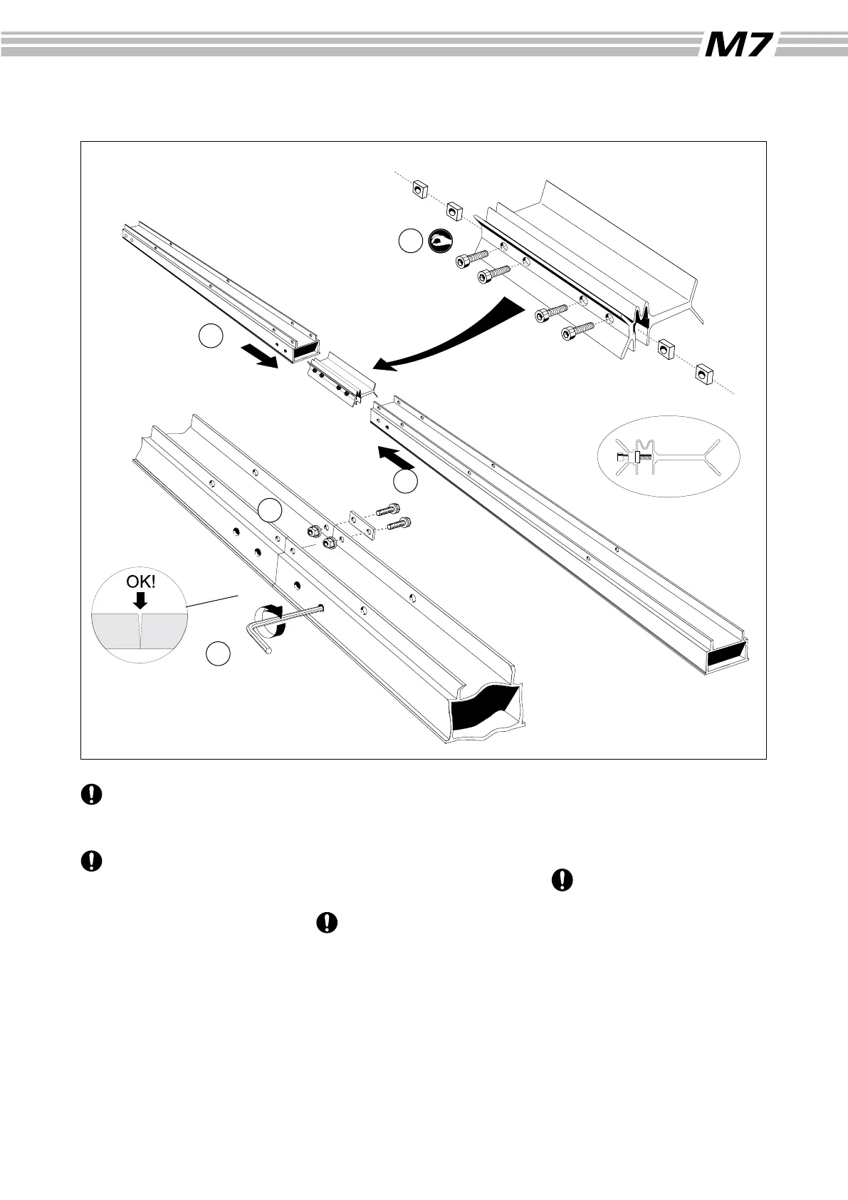
Assembly: Guide Rail
Hole placement in the ends
of the guide rail differs and
must be turned correctly.
Work on a level surface.
Cut the guide rail carton in
half and place the two halves
after each other to form an
underlay where the slide rails
cannot be scratched.
(5) Make sure that the bolts
in the joint coupler are loose.
They should be loosened
approximately one turn from
the point at which they begin to
tighten. (4 x M8x35 allen head
bolts, 4 x M8 square nuts)
(6) Insert the joint coupler in one
end of the rst guide rail section
until the heads of the bolts are
accessible through the side of
the guide rail. Tighten the inner
bolt somewhat.
The joint coupler must
face the right way (see
drawing). The opening must be
turned towards the guide rail
sliding surface.
Coat the sides of the joint
coupler with oil. This is
important to ensure that the
piece expands in the right way
when the bolts are tightened
.
(7) Fit the other guide rail
section over the joint coupler and
push the sections completely
together.
If this is difcult, the reason
can be that the guide rail
sections are not correctly lined
up or that the innermost bolt is
too tight.
(8) Tighten the four allen head
bolts.
(9) Fit the joint plates as shown.
(4 x M6x20 collar bolts, 4 x M6
collar nuts)
6
5
8
7
9
11
Part number Description
4507-001-1000 Guide rail 2.75 m (9ft)
4510-720-6700 Joint coupler 300 mm (12”)
4510-723-0800 Joint plate
4507-001-2072 Screw bag # 72