1
5
4
3
2
6
9
8
7
11
12
13
14
15
16
17
18
19
10
22
21
23
20
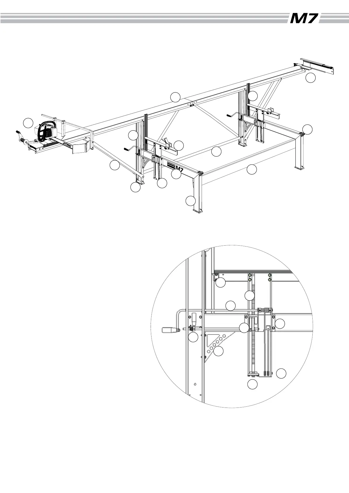
M7 Components
What follows is a brief description of the M7 components
to assist in identifying them during assembly. A more
complete listing is found at the end of the manual.
1 Guide rail
Joint coupler
2 Long leg
3 Horizontal beam
4 Short leg
5 Cross beam
6 Adjusting strut
7 Log bed
Edge support with log clamp
8 Guide rail strut
9 Foot
10 Log rest
11 Knee connector
12 Carriage
13 Log grip
14 Lifting beam
15 Ratchet bar
16 Ratchet bar stop plate
17 Saddle plate
18 Ratchet cam
Ratchet cam axle
19 Ratchet handle
Scale selector plate
Turn spring
20 Crank
Lockring
Lockring with line attachment
21 Plastic slide rail on log bed
Indicator
22 Angle tting
23 Line pulleys
9