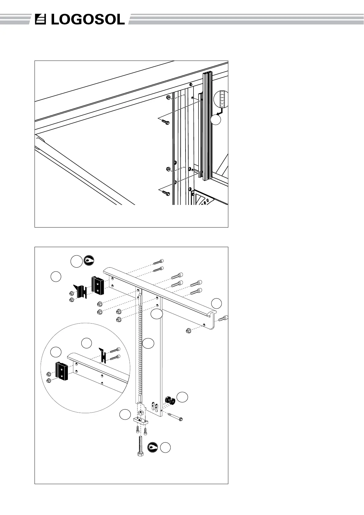
Assembly: Log Bed
(15) Place the plastic slide rail
in the track of the log bed. Fit
the longer scale (A) against the
plastic rail on the right log bed
and the shorter (B) against the
side of the left log bed. Do not
tighten the bolts all the way. (2 x
M6x30 allen head bolts, 2 x M6
collar nuts)
(16) Fit the ratchet bar stop
plate under the lifting beam. (2
x M6x25 allen head bolts)
(17) Fit the line pulleys. (1 x
M6x60 bolt)
(18) Fit the log bed on the lifting
beam. As the bolts will be hard
to screw through the holes,
use an Allen key to pull the
log support down to the lifting
beam. After approx. 20 hours
of use, these bolts will need
to be retightened. (4 x M8x30
self-tapping allen head bolts, 4
x M8 collar nuts)
(C) Fit the bolt for extra support
(1 x M8x16 allen head bolt, 1 x
M8 collar nut)
(19) Fit the rachet bar by
threading the adjustment bolt
(D) through the ratchet bar stop
plate and screwing on the nut.
Do not tighten. Place the bar in
the track of the lifting beam and
tighten the adjusting nut on the
bar until the ratchet bar comes
approx. 5 mm under the upper
edge of the lifting beam. (1 x
M10x40 bolt, 1 x M10 nut)
A
Assembly: Log Side-Rest
(14) Fit the log side-rest. Make
sure that the measuring scales
are both facing in towards the
center of the mill so that the
operator can read both scales
from the center position. (2
x M6x20 bolts, 2 x M6 collar
nuts)
14
14
18
19
B
C
17
15
15
16
D
Part number Description
4507-001-1075 Log support
4507-001-2074 Screw bag # 74
Part number Description
4507-001-1190 Setting block
4507-001-1165 Short indicator
4507-001-1170 Long indicator
4507-001-1150 Ratchet bar
4507-001-1145 Ratchet bar stop plate
4510-723-3900 Line pulley
4507-001-1050 Log bed
4507-001-1065 Lifting beam
4507-001-2074 Screw bag # 74