25
(25)
Slide the edge support onto
the log bed.
(A) Attach the crank handle to
the crank rod by using an 4 mm
Allen key in the screw in the
handle while tightening the nut
(1 x M8 locking nut).
Assembly: Edge Support
16
24
A
A
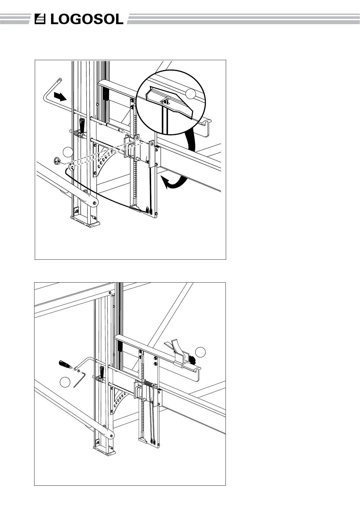
Assembly: Crank and Lifting Line
(24) Thread the lifting line under
the outside pulley of the lifting
beam, straight up and around
the pulley on the horizontal
beam (A) and then down again
to the inner pulley on the lifting
beam.
Fit the crank rod through the
upper holes in the long leg and
through the bushing on the
middle ange.
Place the lifting line in the locking
collar recess. Thread the collar
bushing with the line and the
other collar bushing, on the
crank rod (collars facing out).
Push the crank rod through until
approx. 1/8” extends beyond the
outer saddle plate bushing.
Screw the locking screw of the
locking collars into the recesses
in the crank rod. Then tighten
the
locking screw that is hol-
ding the lifting line.
Part number Description
4507-001-1100 Crank rod
4507-001-1105 Locking collar, track
4507-001-1106 Locking collar
Part number Description
4507-001-1125 Ratchet cam
4507-001-2075 Screw bag # 75
Part number Description
4507-001-1101 Crank handle
4507-001-1025 Edge support, log clamp
4507-001-2075 Screw bag # 75