CAUTION: The LED board is attached to the charging station front cover and the charging
station circuit board. Use care to not place force or strain on the wiring harness when the cover
screws are removed. Failure to do so may result in damage to the charging station, which is not
covered under warranty.
With the (5) Torx screws loosened, hold the front cover in place to avoid strain being placed on the LED board wiring
harness and ip the charging station over on the at surface so that the front cover is on top. Once this is completed,
gently lift the charging station front cover and place to the right side of the charging station unit. Again, use care to
not place force or strain on the wiring harness when the front cover screws are removed. Failure to do so may result
in damage to the charging station.
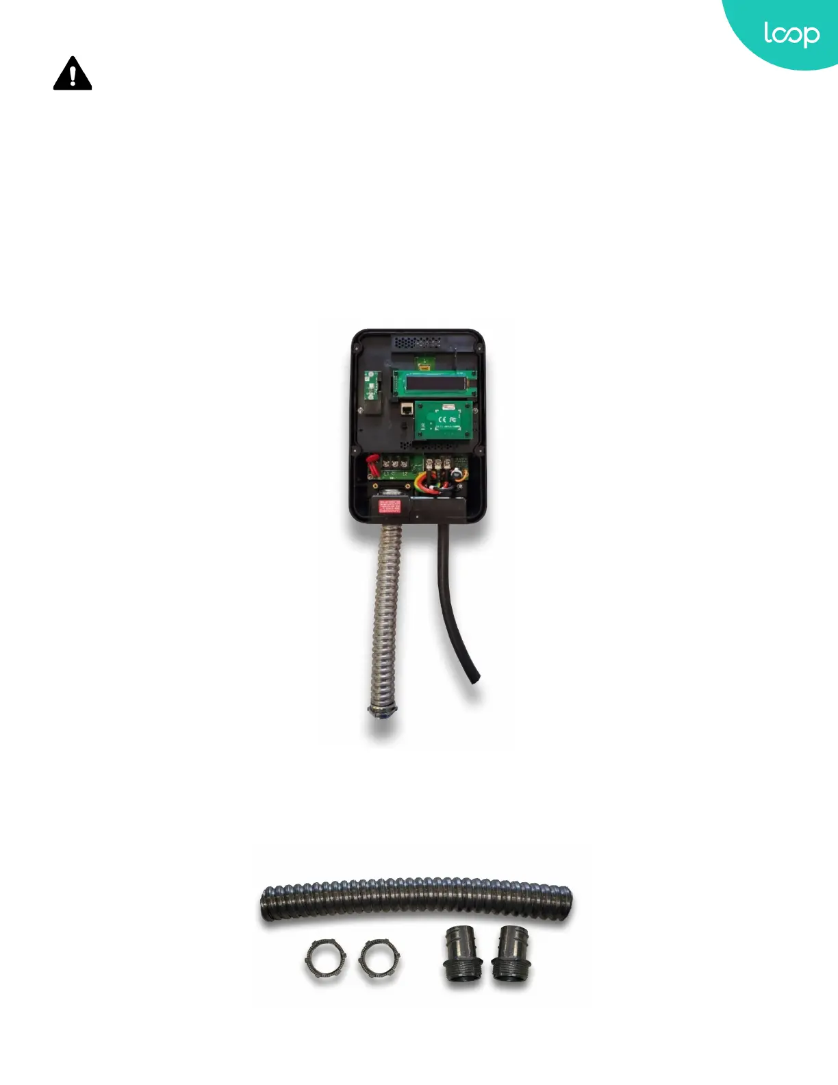
6. Prepare an 11-inch-long 1in diameter ex or rigid conduit in accordance with all applicable state, local and national
electrical codes and standards. Prepare the conduit as shown in gure below
’
Figure 3-7 Loop EV-Flex EVSE with ex conduit attached
7. Assemble the Flex conduit and attach it to the EV, with the lock rings secured.
Figure 3-8 Flex conduit
12
Loop EV-Flex
TM
EVSE
EVS-32A-L2-001 (R-Model)
v.20.9.4
www.evLoop.io