10
1.6
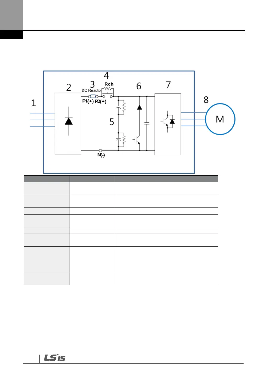
Block Diagram
1 Line power input
3-phase AC line power supply to the
adjustable frequency drive
2 Rectifier
The rectifier bridge converts the AC input
to DC current to supply inverter power
3 P1(+), P2(+) DC reactor wiring connection.
4
Charging
resistor
Restrict inrush current when power is
turned on.
5 Capacitor Bank Stores the DC power.
6
Dynamic
Braking Unit
In above ranges (30~375kW), Braking unit
has to be additionally installed.
7 Inverter
Converts the DC into a controlled PWM
AC waveform for a controlled variable
output
to the motor.
8 Output to motor
Regulated 3-phase output power to the
motor

 Loading...


