71
4 Diagnostics and Troubleshooting
This chapter explains how to troubleshoot a problem when inverter protective functions,
fault trips, warning signals, or faults occur. If the inverter does not work normally after
following the suggested troubleshooting steps, please contact the LSIS customer service
center.
4.1
Trip and Warning
When the inverter detects a fault, it stops the operation (trips) or sends out a warning signal.
When a trip or warning occurs, the keypad displays the information briefly.Detailed
information is shown on the LCD display. When more than 2 trips occur at roughly the same
time, the keypad displays the higher priority fault information. In the keypad, fault trips with
higher priority are displayed first. Use the [Up], [Down], [Left] or [Right] cursor key on the
keypad to view the fault trip information.The fault conditions can be categorized as follows.
•
Level: When the fault is corrected, the trip or warning signal disappears and the fault is
not saved in the fault history.
•
Latch: When the fault is corrected and a reset input signal is provided, the trip or
warning signal disappears.
•
Fatal: When the fault is corrected, the fault trip or warning signal disappears only after
the user turns off the inverter, waits until the charge indicator light goes off, and turns
the inverter on again. If the the inverter is still in a fault condition after powering it on
again, please contact the supplier or the LSIS customer service center.
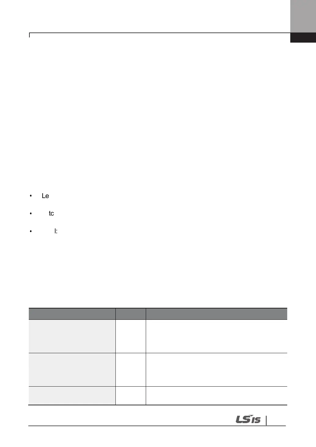
4.1.1 Fault Trips
Protection Functions for Output Current and Input Voltage
Over Load Latch
Displayed when the motor overload trip is
activated and the actual load level exceeds the set
level. Operates when PRT-20 is set to a value
other than ‘0’.
Under Load Latch
Displayed when the motor underload trip is
activated and the actual load level is less than the
set level. Operates when PRT-27 is set to a value
other than ‘0’.
Over Current1 Latch
Displayed when inverter output current exceeds
200% of the rated current.

 Loading...


