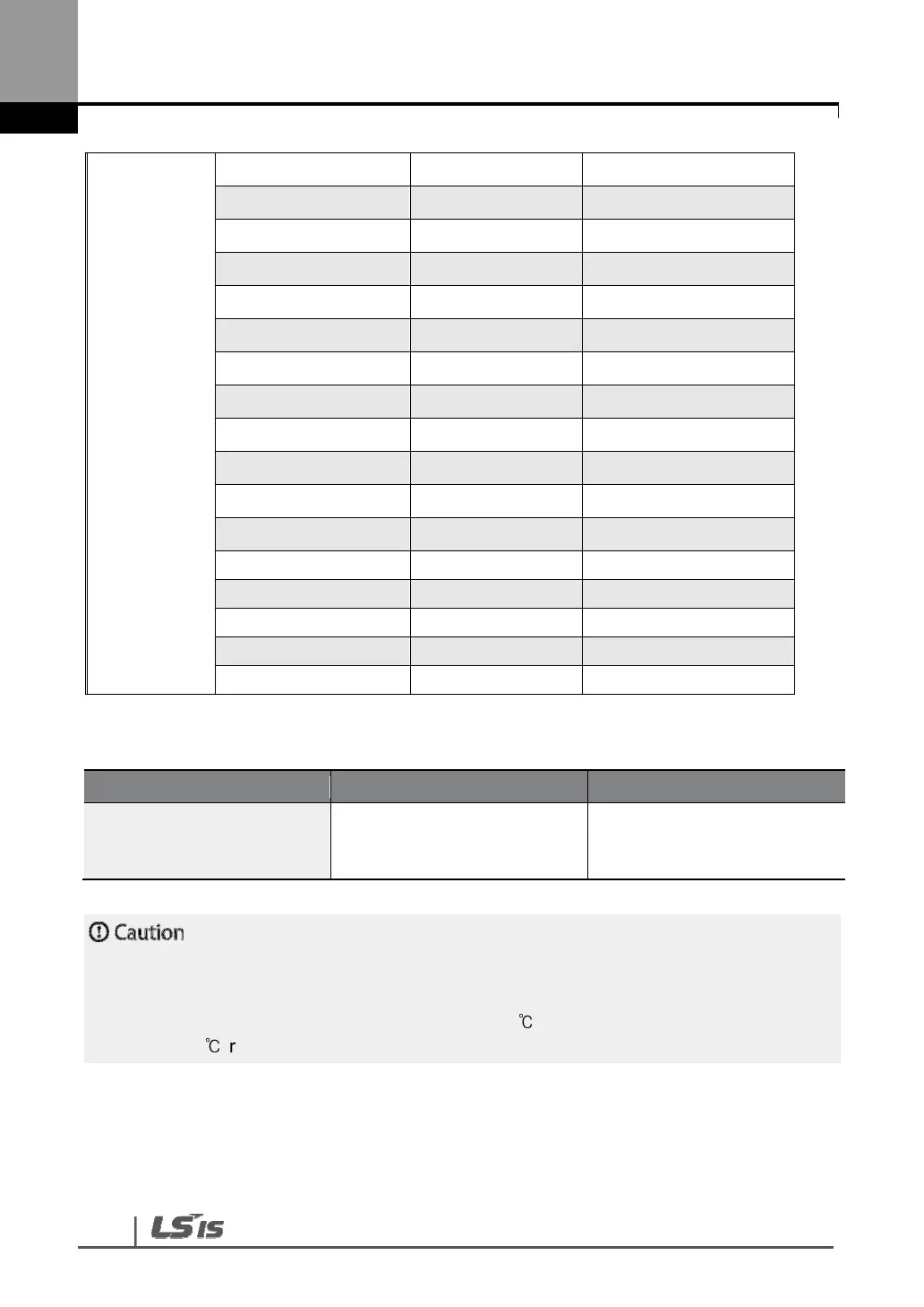
104
11 kW M5 24.5~31.8
15 kW M5 24.5~31.8
18.5 kW M6 30.6~38.2
22 kW M6 30.6~38.2
30~37 kW M8 61.2~91.8
45 kW M8 61.2~91.8
55 kW M8 61.2~91.8
75 kW M8 61.2~91.8
90 kW M12 182.4~215.0
110 kW M12 182.4~215.0
132 kW M12 182.4~215.0
160 kW M12 182.4~215.0
185 kW M12 182.4~215.0
220 kW M12 182.4~215.0
280 kW M12 182.4~215.0
315 kW M12 182.4~215.0
375 kW M12 182.4~215.0
Control Circuit Terminal Screw Specification
P1–
P8/CM/VR/V1/I1/AO/Q1/EG/
24/A1/B1/C1/S+,S-,5G
M3 0.5~0.6 Nm
Apply rated torques to the terminal screws. Loose screws may cause short circuits and
malfunctions. Tightening the screw too much may damage the terminals and cause short circuits
and malfuctions. Use copper wires only with 600 V, 90
℃
rating for the power terminal wiring,
and 300 V, 75
℃
rating for the control terminal wiring.

 Loading...


