35
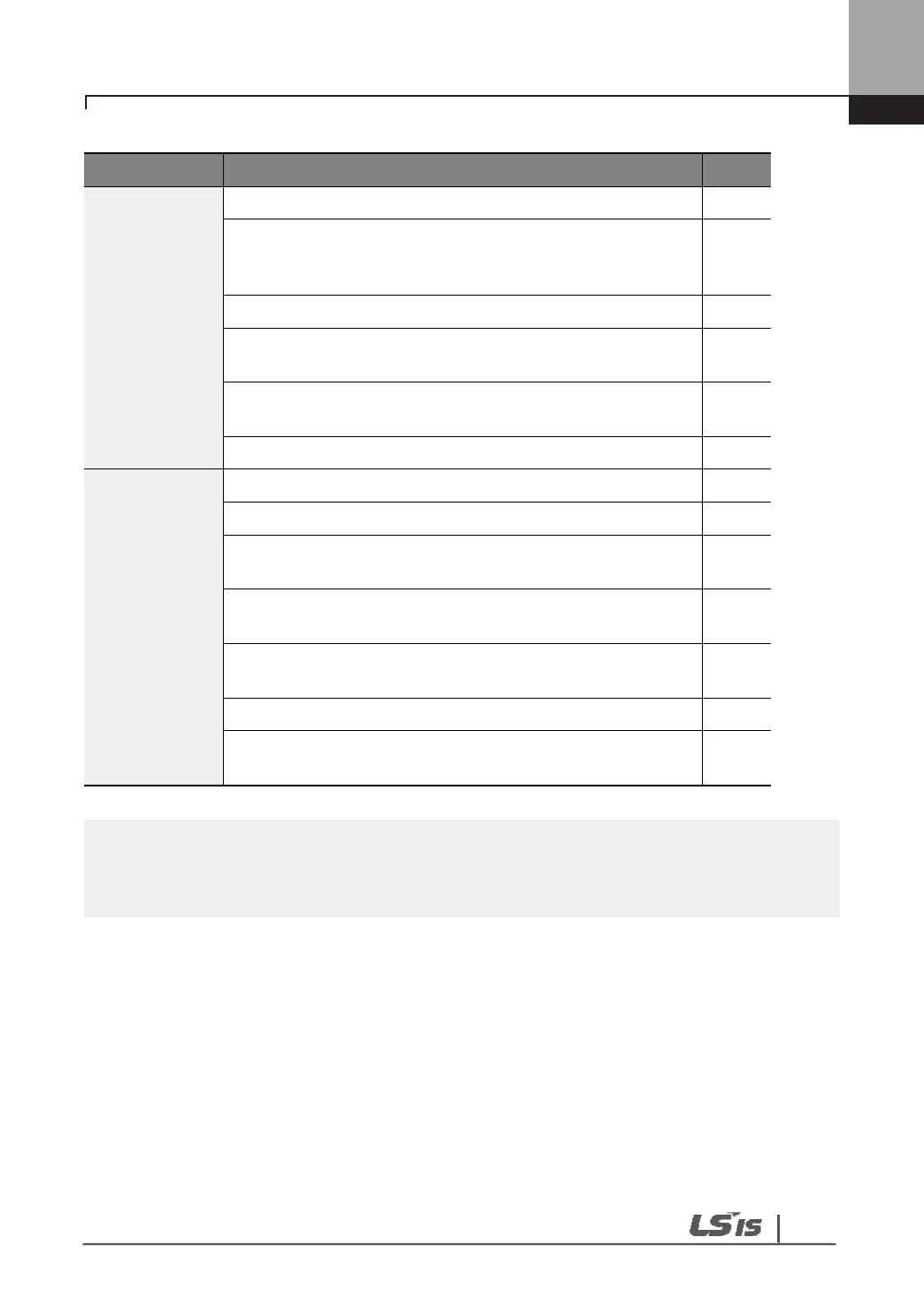
Is the shielding of the STP wiring properly grounded?
If 3-wire operation is required, are the multi-function input
terminals defined prior to the installation of the control
wiring connections?
Are the control cables properly wired?
Are the control terminal screws tightened to their specified
torques?
Is the total cable length of all control wiring < 165 ft (100
m)?
Is the total length of safety wiring < 100 ft (30 m)?
Miscellaneous
Are optional cards connected correctly?
Is there any debris left inside the inverter?
Are any cables contacting adjacent terminals, creating a
potential short circuit risk?
Are the control terminal connections separated from the
power terminal connections?
Have the capacitors been replaced if they have been in
use for > 2 years?
Has a fuse been installed for the power source?
Are the connections to the motor separated from other
connections?
STP (Shielded Twisted Pair) cable has a highly conductive, shielded screen around twisted
cable pairs. STP cables protect conductors from electromagnetic interference.

 Loading...


