Chapter 8 Dedicated Communication
8-2
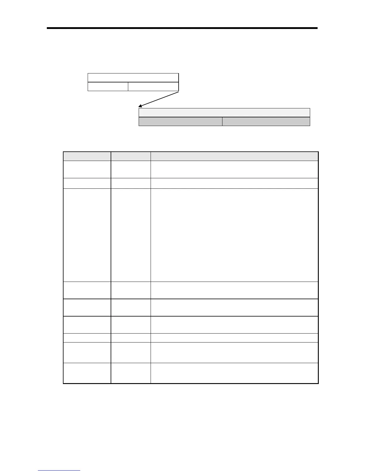
8.1.2 Frame structure
The structure of LS Ethernet module’s application frame is as shown below;
Application Header Format
Application Instruction Format
(1) Header Structure (Application Header Format)
Company ID 8
“LSIS-XGT” + “NULL NULL(reserved area)”
(ASCII CODE : 4C 53 49 53 2D 58 47 54 00 00)
PLC Info 2
* Client(MMI) Server(PLC) : Don’t care (h00)
* Server(PLC) Client(MMI) :
Bit 00~05 : CPU TYPE
01(XGK/R-CPUH), 02(XGK-CPUS), 05(XGI-CPUU)
Bit 06 : 0(Redundancy Master / Single),
1(Redundancy Slave)
Bit 07 : 0(CPU normal operation),
1(CPU error)
Bit 8~12 : System status
1(RUN),2(STOP), 4(ERROR), 8(DEBUG)
CPU Info 1
It is determined to be the XGK/I/R series through a reserved area
XGK: 0xA0,XGI: 0XA4,XGR: 0xA8
Source of Frame 1
* Client(MMI) Server(PLC) : h33
* Server(PLC) Client(MMI) : h11
Invoke ID 2
ID used to discriminate the sequence among frames
(This number is sent as attached to Response frame)
Byte size of application Instructions.
FEnet Position 1
Bit 0~3 : FEnet I/F module’s Slot No.
Bit 4~7 : FEnet I/F module’s Base No.
Reserved 2
(BCC)
1
h00 : Reserved area
(Application Header’s Byte Sum)