Installation
5.
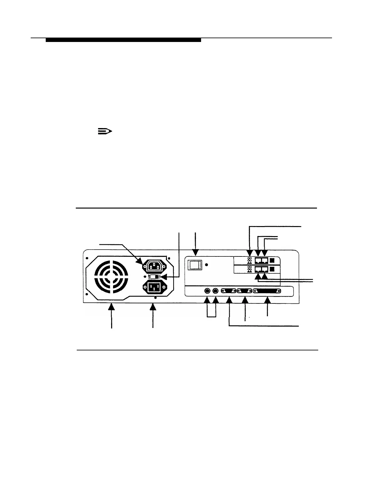
Plug the power cord into the unit’s AC Power IN socket (Figure 2-5).
6.
Check the Voltage Selector Switch to ensure that it is set for your local power
source (Figure 2-5).
7.
Plug the power cord into a properly grounded AC electrical source.
NOTE:
It is strongly recommended that you connect the PARTNER MAIL unit
into the same electrical circuit as the PARTNER II Release 3 so that
the two units share a common ground.
8.
Turn the Power Switch ON (Figure 2-5).
9.
After 2-minutes all Status Indicator Lights should be green indicating that all
PARTNER MAIL system ports are ready to receive calls (Figure 2-5).
Status Indicator Lights
Voltage Selector
Power
Port 4
Not Used
Switch (110V/230V)
Switch
Port 3
Port 1
Port 2
Not
Not
Used Used
Vent
Not
(COM2)
(Do not block)
AC Power IN Used
Remote Maintenance
Device Connector (COM1)
Figure 2-5. PARTNER MAIL Unit - Rear Panel
Installing the PARTNER MAIL Unit
2-9