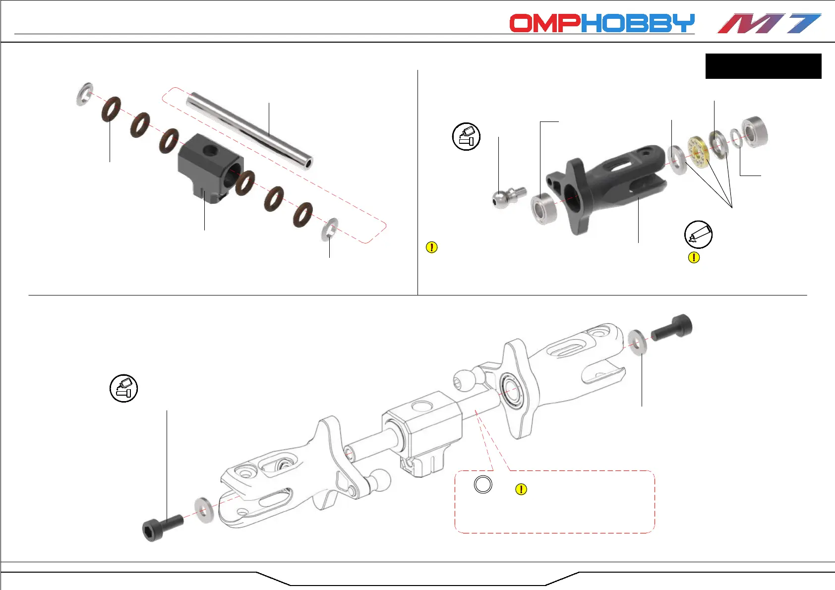
Blade Grip Spacer (×2)
(7-114)
O-Ring 80° Shore
Φ9x2 (×6)
(7-116)
Tail Rotor Yoke (×1)
(7-096)
Tail Rotor Spindle Shaft (×1)
(7-109)
Axial Bearing (×2)
Φ5xΦ10x4
(7-179)
Bearing (×4)
Φ5xΦ10x4
(7-173)
Washer (×2)
Φ3xΦ7x1
(7-182)
Spacer (×2)
Φ5xΦ7x0.5
(7-184)
Ball Joint Screw
M3xΦ6x4.6 (×2)
(7-144)
Hex Screw
M3x8 (×2)
(7-127)
01 Tail Rotor Hub Assembly
02 Tail Rotor Blade Grip Assembly
03 Tail Rotor Head Assembly
Tail Rotor
Blade Grip (×2)
(7-106)
Tail rotor head installation
Page
Large Inner Diameter
(Φ5.3mm)
Small Inner Diameter
(Φ5mm)
The bearing stack might be tricky to
align with the bore in the blade grip.
Assembling the stack on the spindle shaft
and pushing it in that way can make the
installation easier.
The axial bearing cage's open
side must face outward towards the
rotor blade to prevent premature
axial bearing failure.
Your M7 comes with six washers
Φ5xΦ7x0.1. These can be installed
symmetrically between blade grip and
blade grip spacer to increase damping
hardness.
Washer (×6)
Φ5xΦ7x0.1
(7-213)
Glue
Glue
Grease
BAG 10